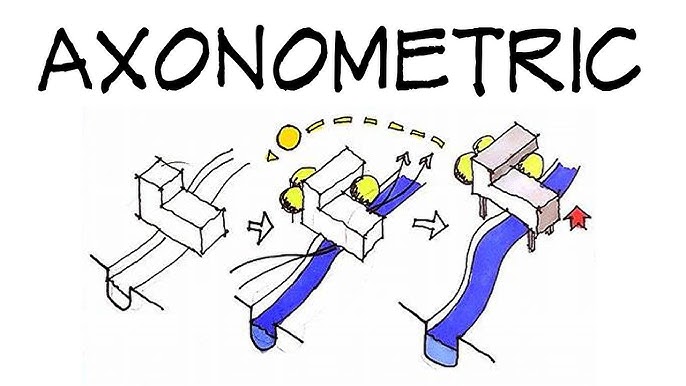
Types & Uses of Axonometric Views for Architects
Axonometric views are among the most essential drawing types in both architecture and engineering. From isometric drawings used in engineering documentation and technical drawing to dimetric and trimetric axonometric views used in architectural presentations, understanding these projection types helps architects, engineers and students communicate design intent clearly and accurately without the distortion of perspective drawing.
This guide covers all three types of axonometric views, explains the difference between isometric and axonometric drawings, and shows you when and why to use each one.
What Is an Axonometric View?
An axonometric drawing is a type of parallel projection where an object is rotated along one or more of its axes to reveal multiple sides. Unlike perspective drawings, axonometric views maintain scale and proportion without vanishing points — making them ideal for technical drawings and conceptual representations.
There are three main types of axonometric views:
1. Isometric View
📐 All axes are equally inclined at 120°.
- Usage: Commonly used in architecture and engineering for clarity and consistency.
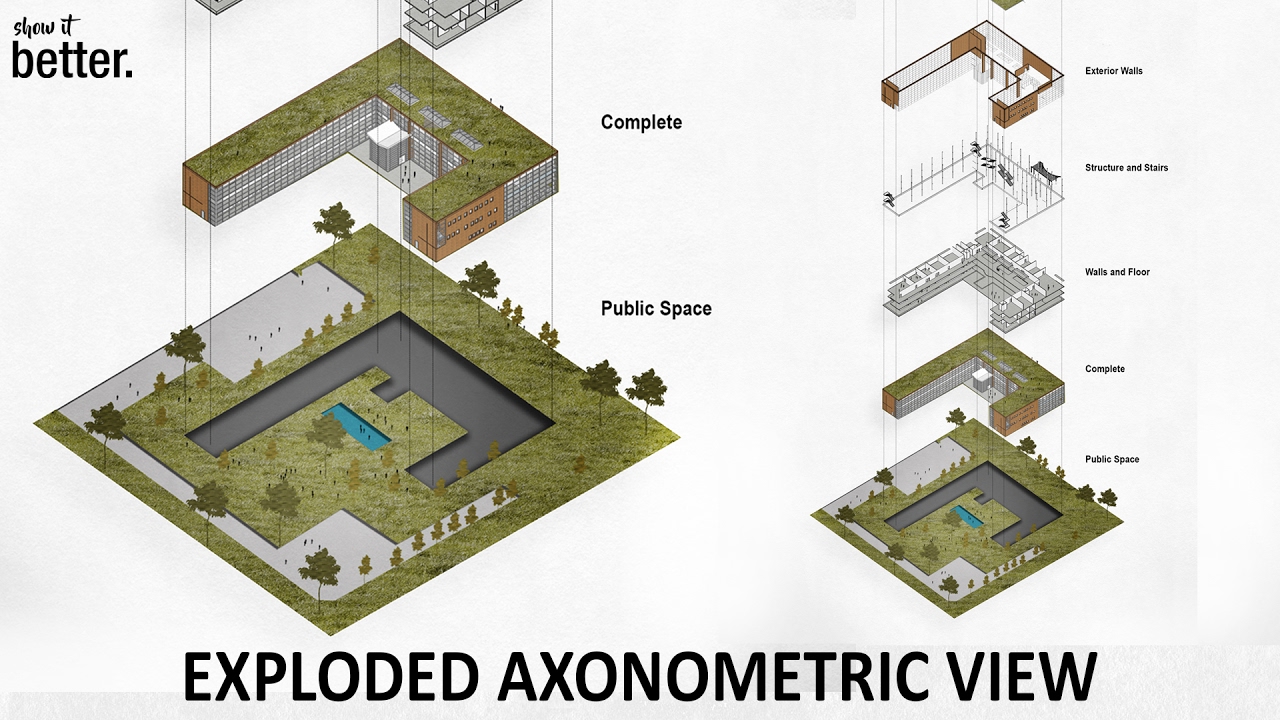
- Why Use It? Isometric drawings offer a clean, distortion-free representation where all axes are scaled equally. Great for floor plans, object detailing, and exploded diagrams.
🔍 Example: Exploded view of a modular furniture system or interior elements within a room.
Isometric View in Engineering Drawing
Isometric view is also one of the most widely used projection types in engineering drawing. In an isometric projection in engineering drawing, all three principal axes are equally inclined to the projection plane and the angles between the axes are 120 degrees. This means all edges parallel to the principal axes are drawn to the same scale — making isometric the preferred choice for technical documentation across civil engineering, mechanical engineering and architectural working drawings.
One important technical detail worth knowing: in a true isometric projection, all dimensions appear reduced to approximately 81.65% of their true length due to foreshortening. In standard engineering drawing practice, however, the full true length is used along all axes for simplicity, and the drawing is understood as an isometric representation. This is why isometric view and isometric projection are often used interchangeably in practice — even though there is a subtle technical difference between them that matters in formal documentation and exams.
2. Dimetric View
🧭 Two axes have equal angles, the third is different.
- Usage: Offers a slightly more realistic sense of depth while still being technical.
- Why Use It? Dimetric views balance visual clarity with a subtle depth effect. They’re useful when focusing on two dominant faces of a structure — such as facades and rooflines.
🔍 Example: Visualizing pavilion structures or rooftop gardens where two dimensions carry more detail.
3. Trimetric View
🔺 All three axes have different scales and angles.
- Usage: Least common in architecture but offers the most natural depth.
- Why Use It? Trimetric drawings mimic real-world perception while still maintaining scale. Best for presentation renders or when highlighting spatial complexity.
🔍 Example: Conceptual sketches for sculptural forms or organically-shaped buildings.
✏️ Pro Tip: Combine axonometric drawings with exploded views, shadow play, and material keys for an eye-catching and informative presentation.
Take your architectural visualisation and design presentation skills further with Kaarwan's Rhino and Grasshopper Professional Course.
Isometric vs Axonometric: What is the Difference?
This is one of those questions that sounds obvious but actually trips up a lot of people — including some who have been using these drawings for years.
Here is the key thing to understand: isometric drawing is actually one specific type of axonometric drawing. It is not a separate category. All isometric drawings are axonometric — but not all axonometric drawings are isometric. Think of axonometric as the umbrella term, and isometric as one option sitting under it alongside dimetric and trimetric.
So what actually separates them?
In an isometric view, all three principal axes are equally inclined at 120 degrees and all edges are foreshortened equally, which gives it that clean, consistent, measurable quality. That is exactly why engineers love it for technical drawings. Everything reads at the same scale across all three dimensions simultaneously.
In dimetric axonometric views, two axes share equal angles while the third is different. The result is a slight visual emphasis on certain faces, useful when a facade or roofline needs more prominence than the other dimension. In trimetric views, all three axes have different scales and angles, which gives the most naturalistic depth effect of the three, but at the cost of measurement consistency.
When do you use which? Isometric is the standard for engineering technical drawings and working documentation where consistent scale across all three dimensions is the point. Dimetric and trimetric axonometric views are better suited for architectural presentations and conceptual visualization where a more natural depth effect is preferred over strict dimensional accuracy.
Quick Comparison — Isometric vs Dimetric vs Trimetric
| Feature | Isometric | Dimetric | Trimetric |
| Axes angles | All equal — 120° | Two equal, one different | All three different |
| Scale | All axes equal | Two axes equal | All axes different |
| Foreshortening | Equal on all axes | Equal on two axes | Different on all axes |
| Best for | Engineering drawings and working documentation | Architectural facades and elevations | Complex spatial forms and conceptual sketches |
| Visual realism | Lower — clean and technical | Medium | Higher — most natural appearance |
Also Read: Top architecture firms in India hiring BIM-skilled architects
Isometric View vs Isometric Projection: Is There a Difference?
Many architecture and engineering students use isometric view and isometric projection interchangeably, and in everyday practice, that is generally fine. But there is a subtle technical distinction worth understanding, especially for exams and formal documentation.
Isometric projection refers to the mathematical method itself — the way a 3D object is oriented so that all three principal axes make equal angles with the projection plane. The result of this mathematical orientation is that all edges appear foreshortened to approximately 82% of their true length.
Isometric view refers to how the object actually appears when that projection method is applied — essentially the visual output of an isometric projection.
Here is where it gets practically interesting. In standard engineering and architecture practice in India, most professionals use true length along all axes for simplicity. This is technically called isometric drawing rather than true isometric projection. The resulting drawing is understood as an isometric representation even though the strict foreshortening is not applied.
For exam purposes and formal technical documentation, understanding this distinction helps you communicate more precisely — and it is the kind of detail that comes up in engineering drawing courses and can catch people off guard.
Why Architects Still Love Axonometric Views
While 3D models and rendering software dominate modern workflows, axonometric drawings continue to serve critical purposes:
- ✔️ Clarity without distortion
- ✔️ Easy comparison between spatial elements
- ✔️ Great for conceptual layouts and diagrams
- ✔️ Helpful in urban design and zoning visualizations
They’re also highly adaptable — often combined with textures, people, shadows, and annotation to tell richer stories.
Where You’ll See Them
- Portfolio presentations
- Competitions & Concept Sheets
- Architectural posters & infographics
- Urban design proposals
- Furniture design layouts
Also Read: Revit vs Archicad vs Tekla Structures: BIM Software Comparison
Conclusion
Axonometric drawings, from isometric to trimetric are foundational skills for every architect, engineer and designer working in the AEC industry. As BIM and digital design tools become standard across architecture and structural engineering workflows, understanding these projection types helps you communicate design intent more clearly in both hand drawings and digital documentation.
Want to build on these drawing fundamentals with professional BIM skills? Kaarwan's BIM and Revit Professional Course teaches you to create accurate architectural documentation — from working drawings and coordination sheets to full BIM models — exactly the skills top architecture and engineering firms look for when hiring.
If you are interested in computational and parametric design with advanced visualisation techniques, Kaarwan's Rhino and Grasshopper course will take your design skills to the next level.
Take your architectural visualisation and design presentation skills further with Kaarwan's Rhino and Grasshopper Professional Course.
Frequently Asked Questions
Q1: What is an axonometric view in architecture?
An axonometric view is a type of parallel projection drawing where a 3D object is represented in 2D by rotating it along one or more axes. Unlike perspective drawings, axonometric views maintain consistent scale and proportion without vanishing points — making them ideal for technical documentation, working drawings and conceptual presentations. The three main types are isometric, dimetric and trimetric views.
Q2: What is the difference between axonometric and isometric drawing?
Isometric drawing is one specific type of axonometric drawing — not a completely separate category. In isometric drawings, all three principal axes are equally inclined at 120 degrees and all edges are foreshortened equally. Other axonometric types — dimetric and trimetric — have unequal axis angles or scales. All isometric drawings are axonometric, but not all axonometric drawings are isometric.
Q3: What is isometric view in engineering drawing?
In engineering drawing, isometric view is a standard method of representing 3D objects where all three principal axes are equally inclined to the projection plane at 30 degrees from the horizontal. All edges parallel to the principal axes are drawn to the same scale. Isometric views are widely used in engineering technical drawings, mechanical component documentation and architectural working drawings because they maintain consistent scale across all three dimensions simultaneously.
Q4: What is isometric projection in engineering drawing?
Isometric projection is the mathematical basis for creating isometric drawings. In a true isometric projection, the object is oriented so all three principal axes make equal angles with the projection plane — resulting in all edges appearing foreshortened to approximately 82% of their true length. In practice, most engineers use full true lengths along all axes for simplicity. Both terms — isometric projection and isometric view — are commonly used interchangeably in engineering and architecture practice, though they are technically distinct.
Q5: By how much are dimensions reduced in an isometric view?
In a true isometric projection, all dimensions along the three principal axes are reduced to approximately 81.65% — commonly rounded to 82% — of their true length. This foreshortening happens because the axes are tilted relative to the projection plane. In standard isometric drawing practice used in most engineering and architecture applications, however, true lengths are used along all axes for simplicity and convenience. The resulting drawing is understood as an isometric representation rather than a mathematically precise isometric projection.
Q6: When should architects use axonometric drawings instead of perspective drawings?
Architects use axonometric drawings when scale accuracy and technical clarity are more important than visual realism. Axonometric views are ideal for working drawings, coordination diagrams, exploded views and portfolio presentations where dimensions need to be readable and consistent. Perspective drawings are better for client presentations and visualization renders where realistic spatial experience matters more than technical precision. Many architects use both — axonometric for documentation and perspective for client communication.