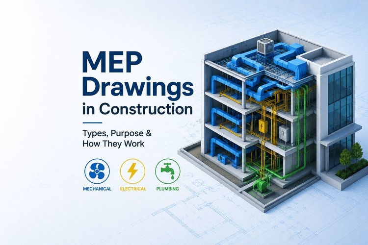
If you have ever stepped onto a construction site and seen that network of ducts, pipes, and cable trays running through ceiling voids, that is the result of a set of MEP drawings that someone spent weeks getting right. MEP stands for Mechanical, Electrical and Plumbing, the three interconnected systems that make a building actually function rather than just stand.
MEP drawings are the technical drawings that show how those systems are designed, coordinated, and installed. Whether you are a student trying to understand MEP works in construction, a junior engineer who just encountered these drawings on your first project, or a CAD drafter building your technical vocabulary, this guide walks you through every drawing type you will encounter on a building project.
Also Read: How BIM Is Shaping the Future of MEP Engineering
What Are MEP Drawings?
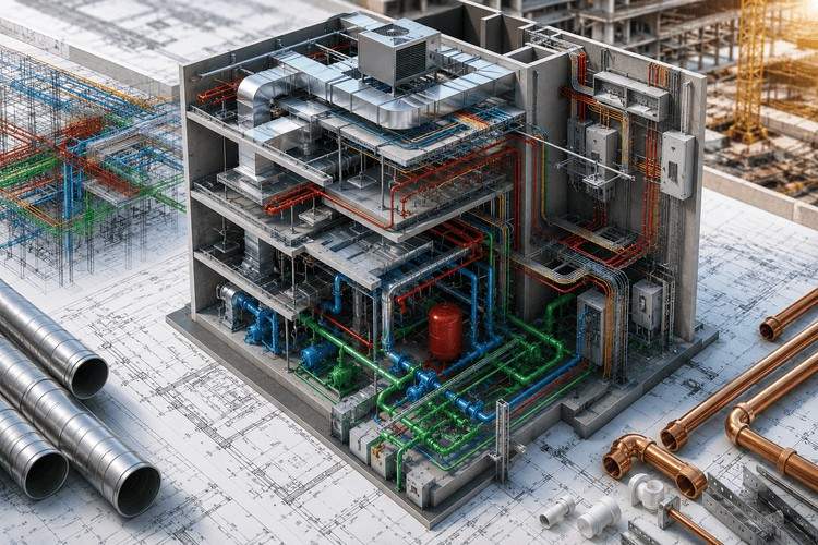
MEP drawings are detailed technical documents produced by MEP engineers to show how a building's mechanical, electrical, and plumbing systems are laid out, connected, and installed. They are different from architectural drawings — architectural drawings show what a building looks like and how spaces are arranged, MEP drawings show how the building functions.
Think of it this way. An architectural drawing shows you a hospital floor plan, the room sizes, corridors, and entrances. The MEP drawings for the same floor show you where the air handling unit is positioned, how the chilled water pipes run to each room, where the electrical panels sit, and how the drainage connects to the main stack. Without the MEP set, you have a shell. With it, you have a building.
MEP drawings full form is Mechanical, Electrical and Plumbing drawings, produced as a coordinated set covering all three building service systems. Contractors, site engineers, project managers, and facility managers all rely on them throughout construction and long after it.
Also Read: MEP Engineers' Guide to bim 2026
Types of MEP Drawings Used in Construction
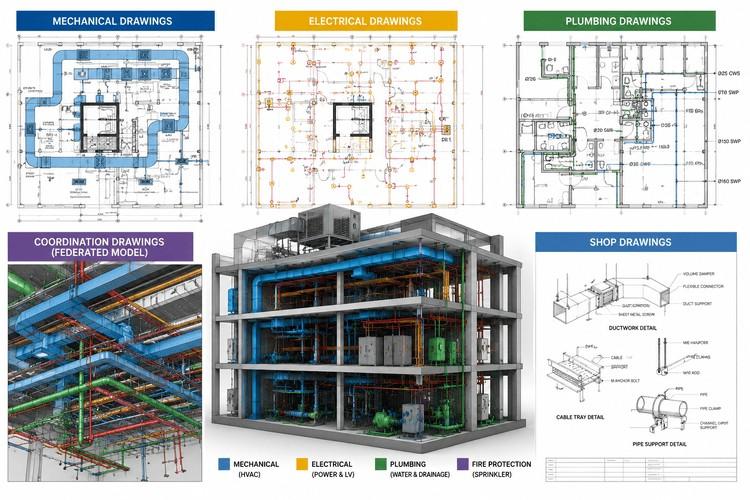
To understand how MEP systems are designed, coordinated, and installed, let's walk through the main types of MEP drawings used on construction projects.
Mechanical Drawings
Mechanical drawings cover the HVAC systems, heating, ventilation, and air conditioning. They show duct routing across each floor, equipment placement (air handling units, fan coil units, chillers, cooling towers), ventilation supply and return air paths, and smoke extraction systems for fire safety compliance.
On a commercial high-rise, the mechanical drawing set is typically the most space-intensive of the three disciplines. HVAC ducts are large, sometimes 1200mm wide, and they run across ceiling spaces that also need to accommodate electrical cable trays and plumbing pipes. The mechanical drawings establish the primary routing early, which is why they drive so much of the coordination work.
Mechanical contractors use these drawings to fabricate ductwork sections off-site and install them in the correct sequence. Site engineers use them to inspect that installation height, orientation, and connection details match the approved design.
Electrical Drawings
Electrical drawings cover everything powered, and in a commercial building, that is a lot. They show the power distribution network (from the main substation down to individual floor panels), lighting layouts with fixture positions and switching zones, cable tray routes, emergency power systems, fire alarm layouts, low-voltage systems including data cabling and security, and earthing and grounding arrangements.
In a data centre, one of the most demanding MEP environments in India's current construction market, electrical drawings become extraordinarily complex. Multiple independent power feeds, precision cooling coordination, redundant distribution systems, and strict clearance requirements make the electrical drawing set the most detailed document in the entire project.
For freshers and junior engineers, the single-line diagram (SLD) is the electrical drawing you will encounter most often. It shows the entire power distribution hierarchy of a building on one sheet, which panels feed which circuits, where the protection devices sit, and what the load is on each branch.
Plumbing Drawings
Plumbing drawings cover water supply, hot and cold water distribution, drainage and sewage, stormwater management, and firefighting and sprinkler networks. They show riser diagrams, vertical pipe runs from basement plant rooms to roof tanks — plumbing plans on each floor, isometric pipe drawings for complex junctions, and fixture schedules listing every tap, basin, and WC by type and location.
Plumbing is the least flexible of the three MEP disciplines in terms of routing. Drainage pipes must slope downward — typically 1% to 1.5% minimum — which means a drain pipe starting at ceiling level on one end of a 15-metre corridor ends up significantly lower on the other end. This creates coordination challenges with HVAC ductwork and cable trays sharing the same ceiling space. Plumbing drawings establish the drainage slopes and riser routes, and everyone else coordinates around them.
Want to create professional MEP drawings instead of just reading them? Enrol in Kaarwan's MEP BIM Certification today.
MEP Coordination Drawings
Coordination drawings are where all three disciplines come together and where most of the real engineering work happens.
A coordination drawing combines the mechanical, electrical, and plumbing systems into one federated drawing set, showing how they share the available ceiling and shaft space. Every system gets assigned a height. Clashes, where two systems try to occupy the same space, are identified and resolved before construction begins.
In BIM-based projects, MEP BIM modelling and clash detection workflows mean coordination drawings are generated directly from the 3D model using tools like Revit MEP and Navisworks. A federated model combines all three discipline models, and automated clash detection runs tests across every intersection, duct against beam, pipe against conduit, equipment clearance against ceiling height. What used to take weeks of manual coordination across 2D drawings can now be completed in days, with a documented record of every clash identified and resolved.
This is why MEP coordination drawings are the most important drawing type in the entire set from a project risk perspective. A clash found in the model before installation costs almost nothing to fix. The same clash found on site, after ductwork has been hung and an MEP engineer discovers a structural beam in the way, can cost weeks of delay and significant rework expense.
Shop Drawings
Shop drawings are the fabrication-ready detail drawings produced for specific MEP components, ductwork sections, pipe assemblies, cable tray brackets, and equipment installation details. They are more detailed than design drawings and are used by fabricators and installation teams rather than design engineers.
A shop drawing for a ductwork section shows the exact dimensions of each duct piece, the connection flanges, the insulation thickness, the support hanger positions, and the sealant requirements at joints. Everything a fabricator needs to manufacture that section in a workshop and a contractor needs to install it correctly on site.
In BIM-based projects, shop drawings are generated from the MEP model — which means dimensions are automatically extracted from the 3D geometry rather than measured from 2D drawings. This eliminates a significant source of fabrication errors and reduces the time between design completion and fabrication start.
What Are MEP Works in Construction?
MEP works in construction refers to the physical installation and execution of mechanical, electrical, and plumbing systems on site — as distinct from the design phase where drawings are produced.
MEP works include installing HVAC ductwork and AHU equipment, laying electrical conduits and cable trays, fixing plumbing pipes and drainage systems, connecting all systems to their respective plant room equipment, and testing and commissioning everything before handover. On a large commercial project, MEP works can represent 30 to 40% of the total construction cost — and MEP works is where most project delays and cost overruns actually originate.
Accurate, well-coordinated MEP drawings are what prevent costly rework and delays during MEP works on site — which is why drawing quality directly affects project timelines and budgets. A poorly coordinated drawing set means installers encounter clashes on site, require field modifications, raise RFIs, and wait for design resolutions before proceeding. Every one of those steps adds time and cost to a project that is already running to a tight schedule.
Also Read: Career Growth Roadmap for MEP Engineers
How BIM Has Changed MEP Drawing Production
Traditionally, MEP drawings were produced in 2D AutoCAD with each discipline working in its own file, largely independently. Coordination was manual — overlaying drawings on a light table or screen to check for clashes. The process was slow, prone to human error, and often failed to catch conflicts until installation was underway.
BIM changed the fundamental logic of how MEP drawings are produced. MEP engineers now model their systems in 3D using Revit MEP ducts, pipes, cable trays, and equipment, all as intelligent objects in a shared model. Design changes automatically update every related drawing sheet. If an engineer changes a duct size in the model, every floor plan, section, schedule, and equipment drawing that references that duct reflects the change immediately.
The coordination process moves from manual overlay to automated clash detection. Navisworks aggregates all discipline models and runs systematic tests, every duct against every structural element, every pipe against every conduit, every piece of equipment against its clearance requirements. Results are documented, assigned, tracked, and re-tested after resolution.
The outcome: projects with BIM-coordinated MEP drawings consistently achieve fewer on-site clashes, faster installation sequences, and more reliable commissioning timelines than those using traditional 2D coordination methods.
Learning to produce MEP drawings in Revit MEP is now the single most important skill gap for MEP engineers in India. It is the difference between a career limited to drafting support roles and one that accesses coordination, BIM management, and project delivery positions at AECOM, WSP, L&T, and Jacobs.
Ready to turn MEP drawings into real-world BIM skills? Start Kaarwan's MEP BIM Certification and build industry-ready expertise.
Frequently Asked Questions About MEP Drawings
What is the full form of MEP drawings?
MEP drawings full form is Mechanical, Electrical and Plumbing drawings. They are a coordinated set of technical drawings produced by MEP engineers to guide the design, coordination, and installation of all building service systems. The three drawing sets — mechanical, electrical, and plumbing — are always produced together as an integrated package because all three systems must share the same building space. A mechanical drawing cannot be finalised without knowing what the electrical cable trays and plumbing pipes are doing in the same ceiling zone.
What are the main types of MEP drawings in construction?
The main types of MEP drawings are mechanical drawings covering HVAC and ventilation systems, electrical drawings covering power distribution and lighting, plumbing drawings covering water supply and drainage, MEP coordination drawings combining all three systems into one federated set for clash detection and spatial coordination, and shop drawings showing fabrication-ready component details for specific elements. Each type serves a distinct purpose at a different stage of the construction process — design, coordination, fabrication, or installation.
What is the difference between MEP design drawings and shop drawings?
MEP design drawings show the intended system layout, routing, and specifications. They are produced during the design phase by MEP engineers and used to communicate design intent and coordinate disciplines. MEP shop drawings show fabrication-ready details for specific components. They are produced during the construction phase by fabricators and contractors, and they show exactly how each element is manufactured and installed. Design drawings guide what to build. Shop drawings guide how to fabricate and install specific components. Both are essential parts of a complete MEP drawing package, and neither can substitute for the other.
How are MEP drawings used on a construction site?
MEP contractors use drawings to install systems in the correct location with correct dimensions, materials, and connection details. Site engineers use them to inspect and verify that installation matches the approved coordination drawings before concealing work behind finishes. Project managers use them to sequence MEP work against structural and architectural activities, ensuring access is available and trades do not conflict on site. Without current, coordinated MEP drawings, on-site work cannot proceed safely, efficiently, or within budget. An MEP team working from outdated drawings is essentially guessing — and those guesses show up as expensive corrections later.
What software is used to create MEP drawings today?
Autodesk Revit MEP is the industry-standard software for BIM-based MEP drawing production in India and globally — it produces all drawing types from a single coordinated 3D model. AutoCAD MEP is used for 2D drawing production on projects that have not yet adopted BIM. Navisworks is used for coordination and clash detection, combining all discipline models and running automated tests across the federated set. Engineers who learn Revit MEP through a structured certification like Kaarwan's MEP BIM certification are able to produce mechanical, electrical, plumbing, and coordination drawings from one model — the standard expected by India's top MEP firms in 2026.