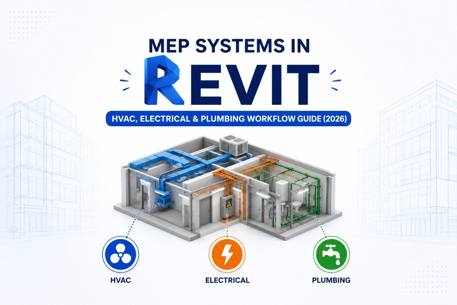
Ask ten people what "learning Revit MEP" actually means day to day, and you'll get ten vague answers about clash detection and coordinated models. True, but not exactly useful when you're staring at a blank Revit file wondering where to even place your first duct.
Most content out there tells you why MEP BIM matters , you probably already know that part. What nobody walks you through is what actually happens once you open the Systems tab: how HVAC, electrical, and plumbing get built inside Revit, discipline by discipline, in the order a real project would demand. That's what we're doing here. No fluff, no repeat of the basics , just the workflow.
Why One Model, Three Disciplines
Here's the thing about Revit MEP that trips up a lot of beginners: it's not three separate tools stitched together. It's one shared model where mechanical, electrical, and plumbing systems all live and breathe in the same coordinate space.
A duct you route on Tuesday can clash with a conduit someone else adds on Wednesday, and Revit will flag it , because everyone's working off the same internal origin, the same levels, the same grids. If you haven't gone through the fundamentals of what MEP BIM actually is and why it replaced isolated CAD drawings, that groundwork is already covered in our beginner's guide to MEP BIM modelling , worth a quick read before this one, since we won't be repeating it. This piece assumes you know the "why" and just want the "how."
HVAC Design Workflow in Revit
1. Place the HVAC Equipment
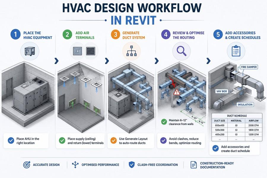
Every HVAC system in Revit begins with an air handling unit (AHU) or similar equipment placed from the Systems tab, usually in a mechanical room, basement, or rooftop, wherever your architectural set has allocated space for it. Get the elevation right in a 3D view before you go further; nothing's more annoying than realising your AHU is floating mid-air three steps later.
2. Add Air Terminals
Next come air terminals: your diffusers, grilles, and registers. Supply terminals typically sit near the ceiling for even air distribution, while return terminals are placed lower down to pull in stale air. Make sure there's enough spacing between them so the supply air doesn't short-circuit straight back into the return before it's done any actual conditioning.
3. Generate the Duct System
Once your equipment and terminals are placed, select them together and let Revit generate the system. The Generate Layout feature under Duct System auto-routes ductwork connecting everything, with tapering built in as duct runs move away from the AHU. It's genuinely one of the more satisfying moments in learning Revit MEP, watching a tangle of disconnected components suddenly become a coherent network.
4. Review and Optimise the Routing
Don't just accept whatever Revit generates, though. Auto-routing is a starting point, not a finished design. Manually reduce unnecessary bends (every elbow adds friction loss), route around structural beams rather than through them, and maintain clearances of roughly 6–12 inches from walls for insulation. Run an interference check against your structural and electrical models early. Catching a duct-versus-beam clash in week two is a minor fix; catching it during site execution is a budget problem.
5. Add Accessories and Create Schedules
Finish with accessories: fire dampers at wall penetrations, volume control boxes for zone regulation, and insulation wherever thermal performance matters. Then generate a duct schedule listing sizes, materials, and airflow requirements. This is what transforms your 3D model into documentation that contractors can confidently build from.
Want to actually build these workflows hands-on instead of just reading about them? Kaarwan's BIM Certification for MEP Engineers walks you through HVAC, electrical, and plumbing modelling with real project files and mentor feedback.
Electrical Systems Workflow in Revit
1. Place Electrical Panels
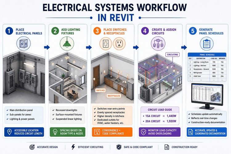
Electrical design in Revit MEP starts with panels: your main distribution panel, sub-panels for specific zones, lighting panels, and power panels. Where you place these matters more than beginners usually assume. Electrical rooms need to remain accessible, and panel location directly affects how far circuits have to travel throughout the building.
2. Add Lighting Fixtures
Next, place lighting fixtures. This is where Revit MEP electrical work becomes more design-driven. Recessed downlights, surface-mounted fixtures, and suspended linear lighting each have their own spacing requirements depending on the room type and lighting needs.
3. Place Switches and Receptacles
Switches are generally positioned near entry points and grouped logically so occupants can control lighting conveniently. Receptacles are distributed along walls at regular intervals, with higher densities in areas such as kitchens and dedicated higher-voltage outlets provided for equipment like HVAC units and water heaters.
4. Create and Assign Circuits
The real payoff for electrical engineers using Revit MEP is circuiting. Select a fixture, create a system, choose the circuit type, and assign it to a panel and breaker. Revit handles the connections automatically. More importantly, circuits carry real load data. Assigning too many fixtures to a breaker can overload the circuit, so monitoring rated capacity (roughly 1,440W on a 15A circuit and 1,920W on a 20A circuit) is essential for a safe and functional design.
5. Generate Panel Schedules
Once circuits are created, Revit automatically generates panel schedules. These schedules update dynamically whenever fixtures are added, removed, or modified. This is one of the biggest advantages of Revit MEP over traditional CAD workflows: documentation stays synchronized with the model instead of requiring manual schedule updates every time a change is made.
Also read: why BIM is the next big step for MEP engineers and our career growth roadmap for MEP engineers if you're mapping this skill against where it actually takes your career.
Plumbing Systems Workflow in Revit
1. Create the Water Supply Network
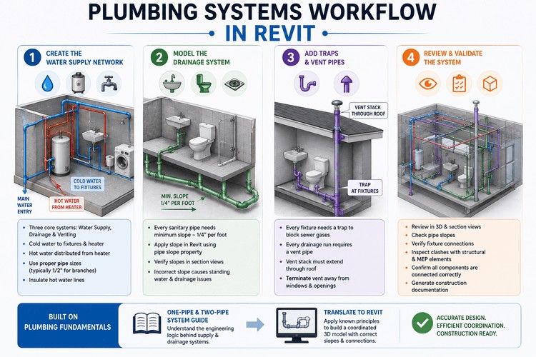
Plumbing in Revit MEP is divided into three core systems: domestic water supply, sanitary drainage, and venting. Water supply starts at the building's main entry point, usually in the basement or mechanical room. Cold water branches out to fixtures and the water heater, while hot water is distributed from the heater to the required fixtures. Pipe sizes should be selected appropriately (typically 1/2" for single-fixture branches) and hot water lines should be insulated to minimise heat loss.
2. Model the Drainage System
Drainage design is where things become more technical. Every sanitary pipe requires a minimum slope of approximately 1/4 inch per foot to ensure gravity-driven flow. Revit allows you to apply this directly through the pipe's slope property and verify it in section views. An incorrect slope can result in standing water and drainage failures.
3. Add Traps and Vent Pipes
Every plumbing fixture needs a trap to prevent sewer gases from entering occupied spaces, and every drainage run requires a vent pipe for proper airflow. In Revit MEP, the plumbing system isn't complete until the vent stack extends through the roof and terminates safely away from operable windows.
4. Review and Validate the System
After modelling the supply, drainage, and vent networks, review the complete system in 3D and section views. Check pipe slopes, verify fixture connections, inspect for clashes with structural or MEP elements, and confirm that all plumbing components are correctly connected before generating construction documentation.
For the underlying engineering logic behind how supply and drainage piping systems are structured , the plumbing fundamentals rather than the Revit-specific steps , our one-pipe and two-pipe system guide covers that ground properly. Once you've got that framework, the Revit side is mostly about translating known engineering logic into a coordinated 3D model with correct slopes and connections.
Coordination Across All Three (Clash Detection Touchpoint)
Once HVAC, electrical, and plumbing all exist in your model, the real test begins , do they actually fit in the same ceiling void without stepping on each other? This is where interference checking earns its keep.
Run it in groups: ductwork against electrical, plumbing against structural, and eventually everything against everything.
There's a rough hierarchy worth knowing , structural elements never move for MEP, HVAC ductwork typically claims the top of the available space because it's the least flexible in terms of slope and clearance, electrical conduit and trays fit into the middle layer, and plumbing generally routes lowest since gravity-fed drainage has strict slope requirements that other systems don't. Resolving a clash usually comes down to adjusting elevation, offsetting a run, or occasionally rerouting entirely.
We've written in depth about clash detection workflows and how coordination actually plays out on real projects, so if this section leaves you wanting more detail, that's intentional , go deeper there rather than here.
Common Beginner Mistakes Across MEP Disciplines
A few patterns show up again and again with people newer to Revit MEP. Skipping proper project setup , units, linked models, levels , before placing a single component, which causes alignment headaches later. Leaving fixtures or equipment unconnected to any actual system, which quietly breaks schedules and load calculations without throwing an obvious error.
Treating clash detection as a final-week task instead of a weekly habit. Getting duct or pipe slopes technically wrong, or ignoring clearance requirements around structural elements. None of these are dramatic mistakes on their own , they're just the small oversights that compound into expensive rework if nobody catches them early.
Still deciding if Revit MEP is worth specialising in? Kaarwan's BIM Certification for MEP Engineers is built specifically for engineers making that CAD-to-BIM shift, with job-ready coordination practice.
FAQs
Do I need to learn all three disciplines (HVAC, electrical, plumbing) or can I specialize?
Most MEP BIM roles do expect familiarity with all three at a working level, since coordination is the whole point , but specialising deeper in one, based on your engineering background, is common and often expected as you move into senior roles.
Is Revit MEP different for electrical engineers vs mechanical engineers?
The core Revit interface stays the same, but the tools you'll use daily differ , electrical engineers live in panel schedules and circuiting, mechanical engineers spend more time in duct systems and equipment sizing.
How long does it take to become proficient in Revit MEP?
Basic single-discipline comfort usually takes four to six weeks of consistent practice; genuine multi-discipline coordination proficiency takes a few months of real project exposure on top of that.
Does Kaarwan's MEP BIM course cover all three systems?
Yes , Kaarwan's BIM Certification for MEP Engineers is structured around HVAC, electrical, and plumbing workflows together, not as isolated modules, since that's how they actually function on real projects.