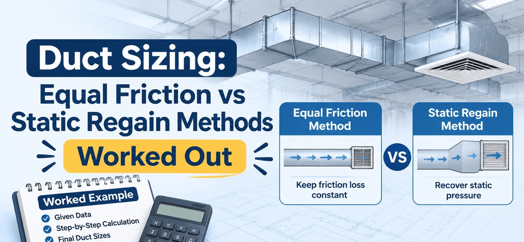
Duct sizing is the process of choosing duct dimensions so each outlet gets its design airflow at an acceptable velocity, noise level and pressure drop.
That sounds tidy. In real life, it's the moment your cooling load meets your ceiling void, and one of them has to give. Pick ducts too small and the system howls and the fan strains. Pick them too big and you've eaten the ceiling, annoyed the architect and paid for sheet metal nobody needed.
This guide shows how duct sizing works, compares the two methods you'll use most, equal friction and static regain, and then sizes the same duct run both ways so you can see the difference in numbers. It sits inside our wider HVAC design guide, so if you're new to the field, read that first.
What is duct sizing and why it matters
Duct sizing is the step in HVAC design where you turn airflow into physical duct dimensions, and it decides how quiet, efficient and buildable the system will be.
Here's why it matters in India. The India Cooling Action Plan, launched by the Environment Ministry in 2018, projects that national cooling demand will grow around eight times between 2017-18 and 2037-38. Every pascal of pressure a fan has to overcome costs electricity, and that's multiplied across thousands of buildings and hours of operation. Small design choices add up.
And it matters on site. A badly sized duct shows up as a noisy diffuser, a far-end room that never cools, a fan motor running hotter than it should, or a main duct that can't clear a beam. You'll hear about it from the client, not from the calculation.
Inputs: airflow per outlet, velocity limits, friction rate
You need three inputs before you size anything: the airflow each outlet must deliver, the velocity you're willing to run, and the friction rate you'll design to.
Airflow per outlet. It comes from your heat load calculation. Each room's supply air follows from its sensible load and the temperature difference between room and supply air. The airflow in each section of duct is simply the sum of every outlet downstream of it. If heat loads are new to you, start with our guide to the heat load calculation.
Duct velocity. Velocity is the quiet governor of the whole design. Faster means smaller ducts but more noise and more fan energy. Slower means quieter ducts but bigger ones. Commonly quoted starting points for offices are around 6 to 7.5 m/s in main ducts, 4 to 5 m/s in branches, and lower again, around 2.5 to 3 m/s, in the final runouts to diffusers. Treat them as starting points. A boardroom needs quieter air than a corridor.
Friction rate. For equal friction, a common starting point is about 0.8 Pa per metre, which is roughly 0.1 in. w.g. per 100 ft. Lower rates give bigger, quieter, more efficient ducts. Higher rates give smaller, noisier ones.
Units help here. Indian practice mixes L/s, m³/h and CFM, and mm for sizes. Use one set per calculation and convert at the end.
Duct sizing methods compared
Three methods cover most duct sizing calculation work, and each answers a different question.
| Method | How it sizes | Best for | Watch out for |
|---|---|---|---|
| Equal friction | Holds one friction rate (Pa/m) along the whole run | Offices, schools, retail, most low-to-medium pressure systems | Short branches get too much air, so you need balancing dampers |
| Static regain | Steps velocity down at each branch so the pressure regained offsets friction in the next section | Long, high-velocity or large VAV systems | More calculation, usually software; slightly larger downstream ducts |
| Velocity reduction | Sets a maximum velocity for each section and reduces it along the run | Quick early sizing, exhaust and noise-sensitive spaces | Doesn't balance pressure; relies on judgement |
If you want the one-line version: equal friction is the workhorse, static regain is the specialist, and velocity reduction is the quick sketch.
Equal friction method, step by step
The equal friction method sizes every section of duct to the same friction loss per metre, so it's quick to do and easy for someone else to check.
- Find the airflow in each section. Add up everything downstream.
- Choose the friction rate. Say 0.8 Pa/m.
- Read the size. Use a duct size chart (ASHRAE's friction chart) or a ductulator, a circular slide-rule or software tool that links airflow, size, velocity and friction. It gives the round duct diameter for each airflow at your friction rate.
- Check velocity. If it's above your limit for that location, drop the friction rate or enlarge the duct.
- Convert to rectangular if needed. Use the equivalent diameter formula below.
- Add fittings and balancing. Elbows, tees and transitions add pressure loss. Short branches need volume control dampers.
De = 1.30 × (a × b)^0.625 ÷ (a + b)^0.25
De is the equivalent round diameter in mm. a and b are the rectangular duct sides in mm. A rectangular duct with the same De gives the same friction as the round one at the same airflow.
Static regain method, step by step
The static regain method sizes ducts so that pressure recovered when air slows down at each branch roughly cancels the friction loss in the next section.
Here's the physics in plain words. When air slows after a takeoff, some of its velocity pressure turns back into static pressure. That's regain. If the next section is sized so the regain equals its friction loss, static pressure at every branch stays about the same. That's why the method is closer to self-balancing.
- Choose a starting velocity for the first section.
- Size the first section: area = airflow ÷ velocity.
- At each takeoff, find the next velocity so that regain equals the next section's friction loss.
- Check the sizes. Round to practical sizes and recheck velocity and noise.
- Add fittings and dampers. You still need volume dampers and a balancing report.
Regain (Pa) = R × (ρ ÷ 2) × (V₁² − V₂²)
R is the regain factor, commonly taken around 0.75. ρ is air density, about 1.2 kg/m³. V₁ and V₂ are the velocities before and after the takeoff in m/s. Set it equal to friction loss (friction rate × section length) and solve for V₂. That's an iterative job, which is why people use software.
Want to size and model duct networks yourself? Practise duct layouts and coordination on real projects in Kaarwan's MEP BIM certification, with mentor feedback.
Worked example: one duct run sized both ways
Let's size the same supply main both ways. This is an illustration with assumed values, not a real project, and every figure below comes from a worked calculation, so rerun it with your own.
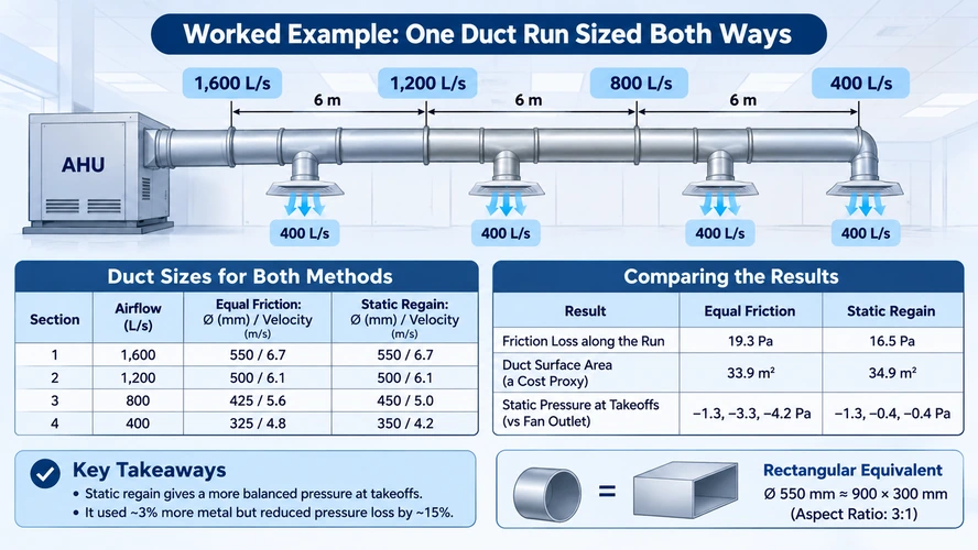
The run. One AHU sends 1,600 L/s down a corridor main. Four takeoffs each draw 400 L/s, with 6 m of duct between them. So the sections carry 1,600, 1,200, 800 and 400 L/s. We size round ducts for clarity and round to the nearest 25 mm. Galvanised steel, air at 1.2 kg/m³, fittings excluded.
Equal friction at 0.8 Pa/m, versus static regain from 6.7 m/s with regain factor 0.75:
| Section | Airflow (L/s) | Equal friction: Ø (mm) / velocity (m/s) | Static regain: Ø (mm) / velocity (m/s) |
|---|---|---|---|
| 1 | 1,600 | 550 / 6.7 | 550 / 6.7 |
| 2 | 1,200 | 500 / 6.1 | 500 / 6.1 |
| 3 | 800 | 425 / 5.6 | 450 / 5.0 |
| 4 | 400 | 325 / 4.8 | 350 / 4.2 |
Comparing the results
| Result | Equal friction | Static regain |
|---|---|---|
| Friction loss along the run | 19.3 Pa | 16.5 Pa |
| Duct surface area (a cost proxy) | 33.9 m² | 34.9 m² |
| Static pressure at takeoffs 1, 2, 3 (vs fan outlet) | −1.3, −3.3, −4.2 Pa | −1.3, −0.4, −0.4 Pa |
Read it like this. Static regain used about 3 per cent more metal and lost about 15 per cent less pressure along the run. More importantly, the pressure at the takeoffs stayed nearly even, within about 1 Pa, while equal friction drifted by about 3 Pa.
That drift is why the first branches over-deliver air, and why equal friction systems need balancing dampers and a proper balancing report. At this scale the numbers are small. On a long, high-velocity run, they add up.
Notice the honest caveat too. Static regain doesn't always give lower total pressure. Here it did because downstream ducts came out slightly bigger. You could get a similar result with equal friction at a lower friction rate. The real advantage of regain is the balanced pressure.
Rectangular equivalent. In a 300 mm ceiling void, the 550 mm round main is equivalent to about 900 × 300 mm, an aspect ratio of 3:1.
Round vs rectangular ducts and aspect ratio
Round ducts are more efficient, while rectangular ducts fit tight ceilings, so most real designs mix them.
Round duct has less friction for the same area, leaks less and is easier to seal. Rectangular duct fits shallow voids and beam-heavy ceilings, which is most Indian buildings. The trade-off is simple: efficiency versus space.
For rectangular ducts, aspect ratio is width divided by height. Keep it at 4:1 or below where you can. Very wide, shallow ducts have more friction, use more sheet metal and can rattle or "oil can" when the fan starts. A square duct is the most efficient, but ceilings rarely allow it.
Flexible duct is useful for the last short connection to a diffuser, but it has far higher friction than metal. Keep it short and straight.
Before you finalise any size, check the structural section. A duct that fits the plan can still hit a beam, and our guide to MEP coordination shows how those clashes get caught early.
Also read: HVAC Heat Load Calculation: Method, Formula & Example
Common mistakes
Most duct sizing problems come from a handful of habits.
- Sizing every duct to a rule of thumb. Do the calculation, even a simple one.
- Ignoring fittings. Elbows, tees and transitions can add as much loss as the straight duct.
- Oversizing "to be safe". Big ducts cost more, eat ceiling space and can give poor air distribution at the diffusers.
- Forgetting the rest of the system. Filters, coils and diffusers often add more pressure drop than the ducts do, so the fan must be chosen against the whole path.
- Skipping the beam check. The section drawing is where duct sizing succeeds or fails.
- Assuming it balances itself. Even static regain needs dampers and a balancing report.
For how duct sizes link back to airflow and equipment, our pillar on HVAC design walks the whole chain. And if you're curious how ventilation shapes a duct network, read our guide to basement and car park ventilation design.
Also read: VRF vs Chiller: How to Choose an HVAC System for Indian Buildings
Codes and references
Duct design relies on a few references. The ASHRAE Fundamentals Handbook has the friction charts and design methods, and our guide to ASHRAE standards for MEP engineers explains how they sit next to Indian codes. SMACNA standards cover duct construction, sealing and pressure classes. NBC 2016 Part 8 covers air conditioning and ventilation in Indian buildings.
If your work involves Revit, you can model duct networks and check them against structure. Start with our guide to designing MEP systems in BIM. For the career side, read about the HVAC design engineer role.
Also read: MEP Drawings in Construction: Types, Purpose & Complete Guide
Size and model duct networks in Revit, from airflow to clash-free layouts, in Kaarwan's MEP BIM certification, guided by industry mentors.
FAQ
Which duct sizing method is best?
Neither wins everywhere. Equal friction is simple and the usual choice for offices, schools and retail. Static regain suits long, high-velocity or large VAV systems, where balanced pressure and lower fan energy justify the extra calculation. Many designs use equal friction for the main layout and static regain only where runs are long.
What friction rate is used for duct sizing?
A common starting point is about 0.8 Pa per metre, which is roughly 0.1 in. w.g. per 100 ft. Lower rates give larger, quieter, more efficient ducts, and higher rates give smaller, noisier ones. The right value depends on the fan's available pressure, the noise limit and how much ceiling space you have.
What is a ductulator (duct sizer)?
A ductulator is a duct sizing calculator, originally a circular slide rule and now usually software. It links airflow, duct size, velocity and friction rate for straight duct, based on ASHRAE's friction chart. It doesn't add fitting losses or check clashes, so it's a starting tool, not the full design.
What velocity is used for main and branch ducts?
For offices, commonly quoted starting points are around 6 to 7.5 m/s in main ducts and 4 to 5 m/s in branches, with lower velocities, around 2.5 to 3 m/s, in final runouts to diffusers. The right figure depends on noise limits, so quiet spaces like boardrooms need lower velocities than corridors.