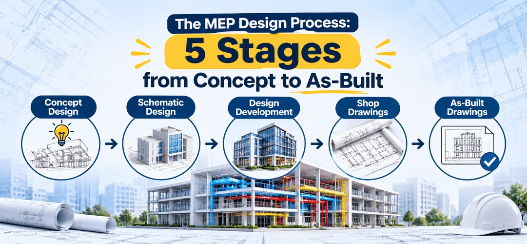
The MEP design process moves through five stages (concept, schematic design, design development, shop drawings and as-built), with each stage adding detail and coordination.
That’s the whole thing in one sentence. But if you’ve ever opened a project folder and seen “DBR”, “BOQ”, “CSD” and “as-builts” sitting side by side, you know the sentence isn’t enough.
The MEP design process is simply the order in which a building’s air conditioning, power, water and fire systems go from a rough idea to something a contractor can install and a facility team can maintain.
This guide walks through each of the MEP design stages, what you hand over at the end of it, who checks it, and where Indian projects tend to trip.
One thing before we begin. Different firms slice this differently. Some talk about SD, DD and CD. Others add construction support at the end. We’re using five stages because they match how most Indian consultancies and contractors actually hand work to each other.
Also Read : MEP Design: The Complete Guide for Engineers (2026)
The 5 stages of the MEP design process at a glance
The five stages of the MEP design process are concept design, schematic design, design development, shop drawings and as-built drawings, and each one ends with a specific set of deliverables that someone has to approve.
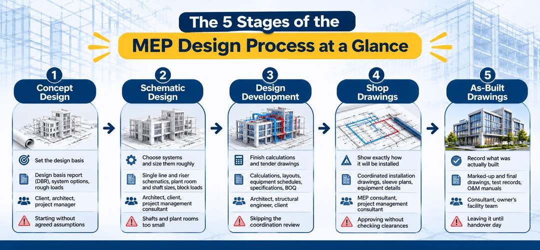
| Stage | Purpose | Key deliverables | Who reviews | Typical mistake |
| 1. Concept design | Set the design basis | Design basis report (DBR), system options, rough loads | Client, architect, project manager | Starting without agreed assumptions |
| 2. Schematic design | Choose systems and size them roughly | Single line and riser schematics, plant room and shaft sizes, block loads | Architect, client, project management consultant | Shafts and plant rooms too small |
| 3. Design development | Finish calculations and tender drawings | Calculations, layouts, equipment schedules, specifications, BOQ | Architect, structural engineer, client, project management consultant | Skipping the coordination review |
| 4. Shop drawings | Show exactly how it will be installed | Coordinated installation drawings, sleeve plans, equipment details | MEP consultant, project management consultant | Approving without checking clearances |
| 5. As-built drawings | Record what was actually built | Marked-up and final drawings, test records, O&M manuals | Consultant, owner’s facility team | Leaving it until handover day |
Read the table once, then keep it open. We’ll take the stages in order, and we’ll follow one imaginary building through all five: a 12-storey office block in Pune. It’s an illustration, not a real project.
Also Read : How to Read MEP Drawings: Symbols, Layers and Legends
Stage 1: Concept design and the design basis report (DBR)
Concept design is where the team agrees what the building needs, and its main output is the design basis report (DBR).
A design basis report is a short document that records the assumptions every later calculation will lean on. Indoor temperature and humidity targets. Outdoor design conditions for the city. Occupancy. Which codes apply. What kind of system goes where. How much backup power the owner wants. If it’s written down at this stage, nobody can quietly change it in month six.
For the Pune office, the DBR might say: air-conditioned floors with a chilled water plant, DG backup for lifts, fire pumps and common areas, NBC 2016 as the main code, and ECBC compliance because the building will be commercial and large. That last one matters. ECBC 2017 applies to new commercial buildings with a connected load of 100 kW or more, or a contract demand of 120 kVA or more, so a building this size can’t treat energy compliance as an afterthought.
Concept stage deliverables usually include the DBR, two or three system options with a rough cost and space comparison, and a first estimate of loads.
What goes wrong here: nobody writes the DBR, or somebody writes it and nobody reads it. Then the HVAC engineer assumes one indoor temperature, the architect assumes another, and the argument shows up three stages later when it’s expensive.
Stage 2: Schematic design
Schematic design chooses the systems and sizes them roughly, so the architect can reserve the space they’ll need.
This is the stage where MEP design deliverables start to look like drawings. You’ll see single line diagrams for power, riser schematics for water and fire, block load estimates, and a first pass at plant room and shaft sizes. Nothing is detailed yet, but the big decisions are being made.
Back to Pune. The team decides on a central chilled water system, one transformer room in the basement, two electrical shafts and two plumbing shafts, and a fire pump room next to the underground fire tank. All of those take space. If the shafts are drawn too small now, someone will be chipping a beam later.
Here’s an observation that’s true on most Indian projects. The architect often wants to freeze ceiling heights early, because it affects façade and floor-to-floor height. Push back, politely, with numbers. One honest conversation about duct depth in the corridor can save months.
What goes wrong here: shafts, plant rooms and ceiling zones get squeezed to make the architecture look cleaner, and the MEP team is handed the leftovers.
Also read: MEP Explained: Full Form, Components & Career Scope
Stage 3: Design development and tender drawings
Design development turns the chosen systems into complete calculations and layouts, and it produces the tender drawings that contractors will price.
This is the heaviest stage. Every discipline completes its calculations: heat loads and equipment selection for HVAC, load estimation and cable sizing for electrical, demand and pipe sizing for plumbing, hydraulic checks for fire fighting. Drawings become real layouts. Equipment schedules list capacities. Specifications describe what quality of material the contractor must supply. A bill of quantities (BOQ) usually follows so contractors can price the job.
Everything also gets checked against architecture and structure at this point. That’s the coordination review. Overlay the services, find the ceiling void that’s too tight, find the duct that meets a beam, and fix it on paper. On the Pune building, this is where the team discovers the main supply duct and the sprinkler main want the same few hundred millimetres above the corridor ceiling.
Two Indian realities show up here. First, fire design must be shaped around NBC 2016 Part 4, and the fire NOC process usually runs in two steps: a provisional NOC at the plan stage and a final NOC before the occupancy certificate. Many states treat buildings of 15 metres and above as high-rise, but the threshold varies by state, so check the local rules. Second, the supply authority will need your load details for the electrical connection.
If you’ve been wondering where drawings and symbols fit in, our guide to MEP drawings in construction covers the types of sheets you’ll see at this stage.
What goes wrong here: teams rush from design development to tender without a proper coordination meeting. Conflicts that could have been red lines become site problems.
Stage 4: Shop drawings
MEP shop drawings are the contractor’s installation drawings, and they show exactly where every duct, pipe, tray and sleeve will go.
This is the stage that confuses freshers most, so here’s the plain version. The consultant’s design drawings show intent: this duct, roughly here, this size. The contractor’s shop drawings show execution: this duct, at this level, with these supports, avoiding that beam, with this clearance for the valve. Shop drawings are prepared by the MEP contractor (or a drawing team working for them), then reviewed and approved by the consultant before anything gets installed.
Typical shop drawing deliverables include coordinated plans and sections for all services, sleeve and opening plans for the structural team, equipment layouts with maintenance clearances, and hanger and support details. On modern projects most of this is built in a 3D model and cut into sheets.
On the Pune building, the contractor’s team overlays HVAC, plumbing, fire and electrical on one combined services drawing (CSD). They find that a cable tray crosses under a chilled water pipe. They re-route it, raise it, and the consultant approves the revised drawing.
What goes wrong here: approvals get rubber-stamped because the schedule is tight. The consultant signs without checking access space, and a valve ends up behind a column.
Stage 5: As-built drawings
As-built drawings record what was actually installed, which is often a little different from what was designed.
During construction, things change. A pipe moves because of a column. A duct drops by 100 mm. A panel shifts to the other wall. As-built drawings capture those changes after installation, along with test records and operation and maintenance (O&M) manuals. The owner’s facility team will use these for the next ten or twenty years.
Think about it from their side. A facility manager at the Pune office gets a call at 2 a.m. because a chilled water valve is leaking. If the as-builts are accurate, they find the isolation valve in minutes. If they’re not, someone is opening ceiling tiles with a torch in their mouth.
Final testing and commissioning records belong here too: air balancing, pressure tests, electrical tests, fire pump runs. Those records often decide whether the final fire NOC and handover go smoothly.
What goes wrong here: nobody collects the marked-up drawings until the day before handover, and by then nobody remembers what changed.
Also read: MEP Systems in Revit: Workflow Guide
Where coordination and BIM fit in the MEP design workflow
Coordination is not a stage of its own. It runs through the whole MEP design workflow, getting more detailed each time.
At concept, coordination means agreeing on space. At schematic, it means reserving shafts and plant rooms. At design development, it means overlaying services and fixing clashes on paper. At shop drawing stage, it means resolving the exact routes before installation. And at as-built, it means recording what changed.
BIM makes this much easier because everyone works on 3D models instead of separate flat drawings. Clash detection tools flag where a duct and a beam occupy the same space before anyone orders material. If you’re building these skills, start with our guide to designing MEP systems in BIM.
Common mistakes at each stage
Most MEP design problems come from the same few habits repeating at different stages.
| Stage | Common mistake | How to avoid it |
| Concept | No signed-off DBR | Write it, circulate it, get a reply in writing |
| Schematic | Shafts and plant rooms undersized | Fight for space early, using rough sizes |
| Design development | Skipping the coordination review | Hold one formal overlay meeting before tender |
| Shop drawings | Rubber-stamp approvals | Check clearances and access on every sheet |
| As-built | Updating drawings at the end | Mark up changes as they happen on site |
Notice that none of these are technical errors. They’re process errors. You can calculate a duct perfectly and still lose a month because nobody agreed on the ceiling height.
Also read: MEP Drawings in Construction: Types, Purpose & Complete Guide
Learn the full MEP design process, stage by stage, with hands-on projects in Kaarwan’s MEP BIM certification, taught by industry mentors.
FAQ
What is the difference between design drawings and shop drawings?
Design drawings, prepared by the consultant, show design intent: system layouts, sizes and specifications. Shop drawings, prepared by the contractor, show exactly how the systems will be installed, with precise routes, levels, supports and clearances. The consultant reviews and approves shop drawings before installation begins.
Who prepares MEP shop drawings?
The MEP contractor prepares shop drawings, usually through an in-house drawing team or a specialist BIM team working for them. The design consultant then reviews them against the design intent and the other trades. Architects and structural engineers also check them where they affect openings, ceilings or loads.
What is a design basis report (DBR)?
A design basis report is a document that records the assumptions behind an MEP design: indoor and outdoor conditions, occupancy, codes, system choices and backup requirements. It’s written at the concept stage and agreed with the client and architect, so later calculations and drawings all follow the same starting point.
How long does MEP design take for a building?
It depends on size and complexity. A small fit-out may take a few weeks of design, while a large hospital or mixed-use project can take many months. Shop drawings and as-builts then continue alongside construction, so the MEP design workflow often runs for the life of the project.
What are as-built drawings?
As-built drawings show what was actually installed, including every change made during construction. They’re prepared after installation by updating the drawings with site changes and test records. Facility teams use them for maintenance, repairs and later renovations, so accuracy matters for the whole life of the building.