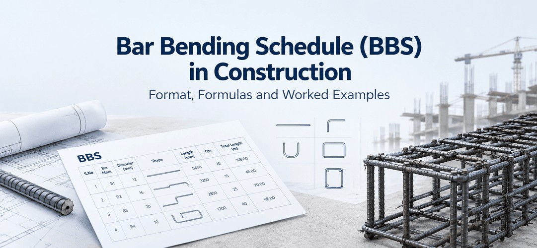
bars, cutting length and weight. The site team uses it to cut and bend steel exactly as drawn, and the estimator uses it to price the steel. This guide gives you the BBS format, the cutting length formulas used with IS 2502 and SP 34, and worked examples for a beam, column, slab and footing.
If you've spent even one day on an Indian site, you've heard someone shout "Is BBS ready?" while the bar benders stand around waiting. That's the whole story of this document. When it's right, steel gets cut once. When it's wrong, you find out after 40 columns are tied.
What is a bar bending schedule (BBS)?
A BBS is a tabular list of the reinforcement in an RCC member. Each row is one bar type, and it tells the bar bender which bar to cut, how long to cut it, where to bend it, and how many to make.
Think of it as the translation layer. The structural drawing shows the designer's intent, with bar marks, spacings and sections. The BBS turns that into numbers a bar bender can act on and a quantity surveyor can bill against.
Why is a BBS needed on an Indian site?
Here's the odd thing about steel. You order it by weight, in tonnes, but you cut it by length. Something has to connect the two, and that something is the BBS.
- Ordering: TMT bars (usually Fe500D these days) arrive in roughly 12 m stock lengths. The BBS tells you how many cutting pieces you can get from each bar, and where the offcuts will go.
- Billing: Running account bills and steel reconciliation both lean on it. When the contractor and the client's engineer disagree on tonnage, the BBS is the document everyone reaches for.
- Wastage: A bar cut 30 mm short is a rejected bar. A bar cut 30 mm long, across a few thousand pieces, is a surprising pile of scrap.
- Rolling margin: Bars are sold by weight, but real bars rarely weigh exactly the theoretical d²/162. IS 1786 allows a small tolerance on nominal mass, and that tolerance is why your reconciled weight never matches your BBS to the last kilo.
A rough site thumb rule often quoted for low-rise buildings is 3 to 4 kg of steel per sq ft of built-up area. Use it as a sanity check on your total, never as a substitute for the schedule.
Picture a G+2 house where the bar bender works from the drawing alone. Every stirrup is "about right," and about right over a few hundred stirrups becomes a tonne of questions at billing time. The BBS is what stops that conversation.
Want to see where the BBS sits among the other paperwork on a live project? Here's where a BBS fits in site documents.
Want to see rebar modelled and scheduled in Revit instead of by hand? Explore Kaarwan's BIM Certification Program for Civil Engineers and learn the workflow.
BBS format: what each column means
There's no single mandatory layout. Firms tweak it. But a working BBS usually carries these columns:
| Bar mark | Member | Dia (mm) | Shape | No. of members | Bars per member | Total bars | Cutting length (m) | Total length (m) | Unit wt (kg/m) | Total wt (kg) |
| B1-1 | Beam B1 | 16 | Straight | 1 | 3 | 3 | 4.010 | 12.03 | 1.580 | 19.01 |
| B1-3 | Beam B1 | 8 | Stirrup | 1 | 25 | 25 | 1.165 | 29.13 | 0.395 | 11.50 |
A quick tour:
- Bar mark: A unique tag for each bar type, such as B1-1 or C1-V. Keep it identical across the drawing, the BBS and the bar bender's job card.
- Shape: The shape code or sketch, per IS 2502 and SP 34.
- Total bars: Members × bars per member.
- Cutting length: The straight length of bar stock you cut before bending. This is the number everything else depends on.
- Total length: Total bars × cutting length.
- Total weight: Total length × unit weight.
You'll also see the table called a BBS table or schedule format in some offices. Same thing.
Which IS code is used for a bar bending schedule?
No single code covers all of it, which trips up a lot of freshers. In practice you lean on a small set:
- IS 2502: Code of practice for bending and fixing of bars. It covers bar shapes, bending and hooks.
- SP 34: The handbook on concrete reinforcement and detailing. It's where the schedule format and detailing practice live.
- IS 456:2000: Cover (Cl. 26.4), development length and anchorage (Cl. 26.2), and laps.
- IS 1786: The TMT bar specification, including grades and mass tolerance.
- IS 13920: Ductile detailing for seismic zones, which is why stirrups keep their 135° hooks.
Always check the current edition on the BIS website before you quote a clause in a deliverable. If you want the wider picture, here are the IS codes every civil engineer should know.
How to prepare a bar bending schedule, step by step
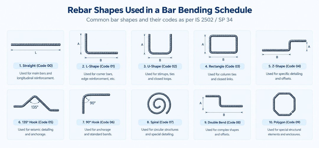
- Read the drawing properly: Get member sizes, bar marks, diameters, spacings, cover and any notes. Resolve conflicts now, not after cutting.
- Fix your conventions: Cover, hook type, bend deductions and rounding. Write them at the top of the sheet.
- Sketch each bar shape: Even a rough sketch makes the bends obvious.
- Work out each cutting length: Use the formulas in the next section.
- Count the bars: For spaced bars: (length − 2 × cover) ÷ spacing, rounded up, plus one.
- Fill the table, member by member: Footing first, then columns, beams, slabs, floor by floor.
- Compute weights: Total length × d²/162, per diameter.
- Get it checked: Someone other than the preparer should verify at least one bar of each shape.
Laps and anchorage lengths come from the drawing and IS 456. Take them from there rather than from memory.
Cutting length formulas: straight bar, bent-up bar, stirrup, hooks and bends
Every BBS calculation boils down to one line:
Cutting length = sum of straight outside dimensions + hooks − bend deductions
Every formula below is that same line, dressed differently.
| Item | Formula |
| Straight bar | Length − 2 × cover (plus any anchorage shown on the drawing) |
| Bend deductions | 45° = 1d, 90° = 2d, 135° = 3d, 180° = 4d |
| Stirrup hook (135°) | Extension of 10d is common on site; IS 13920 asks for at least 6d and not less than 65 mm |
| Rectangular stirrup | 2(a + b) + 2 × 10d − 3 × 2d − 2 × 3d, where a and b = member size − 2 × cover |
| Crank (bent-up) bar | Add 0.42D for a 45° crank, where D = crank height |
| Unit weight | d² ÷ 162 kg/m (d in mm) |
| Number of spaced bars | (Length − 2 × cover) ÷ spacing, rounded up, + 1 |
One more thing worth separating in your head. IS 456 gives an anchorage value for bends and hooks, for example 16d for a standard U-hook. That's about how much development length the hook is worth, not how much extra bar you cut. Don't mix the two.
Quick check on the weight formula. 8 mm bar: 8² ÷ 162 = 0.395 kg/m. 10 mm: 0.617. 12 mm: 0.889. 16 mm: 1.580.
Bent-up bars and bend allowances
A bent-up (cranked) bar rises from the bottom of a slab to the top over the support. Why bother? The bar picks up shear and hogging near the support instead of stopping dead.
The extra length that crank adds comes from plain geometry. For a crank of height D at angle θ, the extra length is D × (cosec θ − cot θ):
- 30° crank → about 0.27D
- 45° crank → about 0.42D
- 60° crank → about 0.58D
On Indian sites, 45° is the one you'll use nine times out of ten. In simply supported slabs, alternate bottom bars are often cranked at roughly L/7 from the support. And remember each crank has two bends, so a bar with two cranks has four 45° bends. That's four deductions of 1d.
Worked examples: beam, column, slab and footing
Assumptions for all four: Fe500D bars, clear cover as stated, 135° stirrup hooks with 10d extension, bend deductions of 1d/2d/3d/4d, unit weight d²/162, and cutting lengths rounded to the nearest 5 mm.
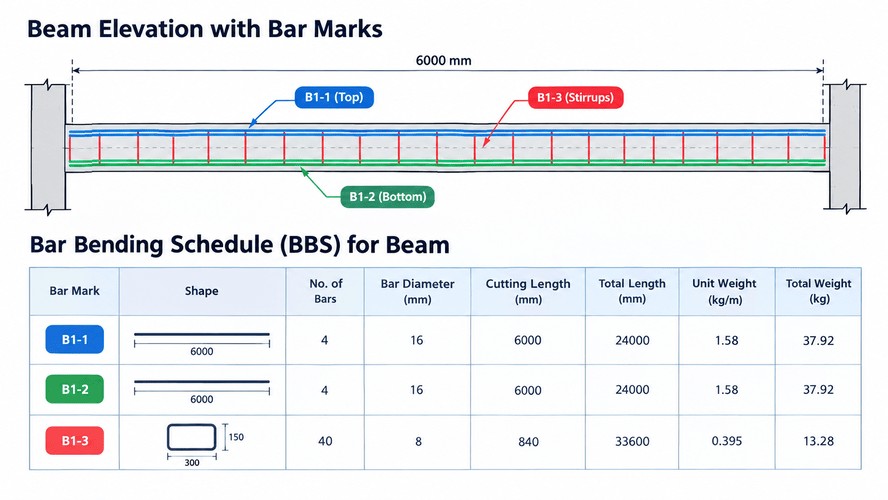
Bar bending schedule for beam
Given: Beam B1, 250 × 400 mm. Clear span 3,600 mm, supports 230 mm wide, clear cover 25 mm. Bottom 3 nos of 16 mm, top 2 nos of 12 mm, two-legged 8 mm stirrups at 150 mm c/c.
- Main bars: 3,600 + 2 × (230 − 25) = 4,010 mm.
- Stirrup: a = 250 − 50 = 200 mm, b = 400 − 50 = 350 mm. Cutting length = 2(200 + 350) + 160 − 48 − 48 = 1,164 mm, taken as 1,165 mm.
- Number of stirrups: (3,600 − 50) ÷ 150 = 23.67, rounded up to 24, plus 1 = 25.
| Bar mark | Dia (mm) | Shape | Nos | Cutting length (mm) | Total length (m) | Unit wt (kg/m) | Weight (kg) |
| B1-1 | 16 | Straight | 3 | 4,010 | 12.03 | 1.580 | 19.01 |
| B1-2 | 12 | Straight | 2 | 4,010 | 8.02 | 0.889 | 7.13 |
| B1-3 | 8 | Stirrup | 25 | 1,165 | 29.13 | 0.395 | 11.50 |
Total weight: 37.64 kg.
Bar bending schedule for column
Given: Column C1, 300 × 300 mm, floor height 3,000 mm, clear cover 40 mm. Vertical bars 4 nos of 16 mm and 4 nos of 12 mm with a lap of 50d above (as assumed for this example; take the real lap from your drawing and IS 456). Ties are 8 mm at 150 mm c/c.
- 16 mm bars: 3,000 + 50 × 16 = 3,800 mm.
- 12 mm bars: 3,000 + 50 × 12 = 3,600 mm.
- Tie: a = b = 300 − 80 = 220 mm. Cutting length = 2(440) + 160 − 96 = 944 mm, taken as 945 mm.
- Number of ties: (3,000 − 80) ÷ 150 = 19.47, rounded up to 20, plus 1 = 21.
| Bar mark | Dia (mm) | Shape | Nos | Cutting length (mm) | Total length (m) | Unit wt (kg/m) | Weight (kg) |
| C1-1 | 16 | Straight | 4 | 3,800 | 15.20 | 1.580 | 24.02 |
| C1-2 | 12 | Straight | 4 | 3,600 | 14.40 | 0.889 | 12.80 |
| C1-3 | 8 | Tie | 21 | 945 | 19.85 | 0.395 | 7.84 |
Total weight: 44.66 kg. A real column would usually have closer tie spacing near the joints, so treat this as the simple case.
Bar bending schedule for slab
Given: One-way slab S1, 3,000 × 4,000 mm clear, 150 mm thick, supported on 230 mm walls, clear cover 20 mm. Main bars are 10 mm at 150 mm c/c, with alternate bars cranked at 45°. Distribution bars are 8 mm at 200 mm c/c. This schedule covers the bottom steel only. Top steel over supports is scheduled the same way.
- Straight main bar: 3,000 + 2 × (230 − 20) = 3,420 mm.
- Crank height: D = 150 − 20 − 20 − 10 = 100 mm.
- Cranked main bar: 3,420 + 2 × 0.42 × 100 − 4 × 10 = 3,464 mm, taken as 3,465 mm.
- Main bar count: (4,000 − 40) ÷ 150 = 26.4, rounded up to 27, plus 1 = 28. That gives 14 straight and 14 cranked.
- Distribution bars: length 4,000 − 40 = 3,960 mm. Count is (3,000 − 40) ÷ 200 = 14.8, rounded up to 15, plus 1 = 16.
| Bar mark | Dia (mm) | Shape | Nos | Cutting length (mm) | Total length (m) | Unit wt (kg/m) | Weight (kg) |
| S1-1 | 10 | Straight | 14 | 3,420 | 47.88 | 0.617 | 29.54 |
| S1-2 | 10 | Cranked | 14 | 3,465 | 48.51 | 0.617 | 29.93 |
| S1-3 | 8 | Straight | 16 | 3,960 | 63.36 | 0.395 | 25.03 |
Total weight: 84.50 kg.
If you want to go deeper on slabs and beams separately, we'll be covering each in its own guide.
Bar bending schedule for footing
For an isolated footing, the BBS must account for the footing dimensions, clear cover, bar spacing, and the length of the upturned ends.
Given: Isolated footing F1, 1,500 × 1,500 mm, 400 mm deep, clear cover 50 mm (the IS 456 minimum for footings). Bottom mesh of 12 mm bars at 150 mm c/c both ways, with 90° ends turned up 200 mm.
- Cutting length: (1,500 − 100) + 2 × 200 − 2 × 2 × 12 = 1,752 mm, taken as 1,750 mm.
- Bars per direction: (1,500 − 100) ÷ 150 = 9.33, rounded up to 10, plus 1 = 11. That's 22 bars across both directions.
| Bar mark | Dia (mm) | Shape | Nos | Cutting length (mm) | Total length (m) | Unit wt (kg/m) | Weight (kg) |
| F1-1 | 12 | L-bent | 22 | 1,750 | 38.50 | 0.889 | 34.23 |
Total weight: 34.23 kg per footing. Four identical footings come to about 136.9 kg. The column starter bars are counted with the column, not here.
BBS in Excel and software
Most Indian offices still build the BBS in Excel, and honestly, it works. Set up one row per bar mark and let the sheet do the arithmetic:
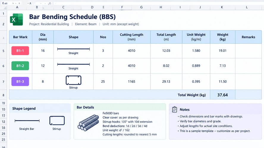
- Cutting length column, entered or built from the formulas above
- Total bars = members × bars per member
- Total length = total bars × cutting length ÷ 1000
- Unit weight = dia² ÷ 162
- Total weight = total length × unit weight
Add a subtotal by diameter, because that's what you order. Print it to PDF for the bar bender and the store. If you use dedicated BBS software, it still needs a check. Verify one bar of each shape by hand before you trust the output.
From BBS to a Revit rebar schedule
Once reinforcement is modelled in Revit, the schedule is no longer typed by hand. It's generated from the model, bar marks and all, so a change in the beam updates the quantities. If you want to see how that works, here's how to extract rebar quantities from a Revit model, and how reinforcement is modelled for fabrication. Kaarwan's BIM Certification Program for Civil Engineers covers rebar modelling, schedules and take-offs.
Tired of re-checking schedules and quantities manually? Kaarwan's BIM Certification Program for Civil Engineers covers rebar, steel and fabrication, plus schedules, BOQs and take-offs.
Common BBS mistakes on site
- Forgetting bend deductions, so the cage won't fit the formwork.
- Using nominal cover where the BBS needs clear cover.
- Skipping anchorage at supports, which is where quantity disputes start.
- Ignoring laps when a member is longer than the 12 m stock bar.
- Reusing bar marks for different bars across drawings.
- Rounding bar by bar instead of rounding the total.
- Not checking the first bent cage against the BBS before mass cutting begins.
- Forgetting that purchase is by weight, so the rolling margin will always show up.
Catch these on paper and the pour day takes care of itself.
FAQs
What is a bar bending schedule?
t's a table listing every bar in a structural member: mark, diameter, shape, number, cutting length and weight. Site teams use it to cut and bend steel, and estimators use it to price it.
How do you prepare a bar bending schedule?
Read the drawing, fix your cover and hook conventions, sketch the bar shapes, calculate each cutting length, count the bars, fill the table, work out weights, and have someone check it.
How do you calculate cutting length in a bar bending schedule?
Add the straight outside dimensions and the hooks, then subtract the bend deductions: 1d, 2d, 3d and 4d for 45°, 90°, 135° and 180° bends.
Which IS code is used for a bar bending schedule?
IS 2502 covers bending and fixing of bars, SP 34 covers detailing and schedule format, and IS 456:2000 covers cover and laps. Check the current editions on the BIS website.
What is a bar mark in a bar bending schedule?
A bar mark is the unique tag given to each bar type, for example B1-1 for the bottom bars of beam B1. It links the drawing, the schedule and the bar bender's job card.
How do you make a bar bending schedule in Excel?
Make one row per bar mark with columns for diameter, shape, bar count, cutting length, total length, unit weight (dia² ÷ 162) and total weight, then subtotal by diameter.
What is the difference between a BBS and a bill of quantities?
A BBS lists the steel bar by bar, with lengths and shapes, to cut and bend it. A bill of quantities lists all the items of work with quantities and rates, and the BBS total feeds its steel item.