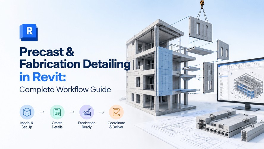
Precast and fabrication detailing in Revit is the process of taking a structural model past design intent and pushing it all the way to LOD 400 - the point where the model itself, not a hand-drafted sheet, is what a factory actually manufactures from. That means splitting walls and slabs into real precast panels, embedding reinforcement and lifting hardware, generating shop drawings straight off the model, and exporting data that CNC and casting-bed equipment can read directly. If you've spent any time around a Revit precast workflow, you already know this is where "coordination model" stops being enough and "fabrication model" takes over.
This guide walks through that whole pipeline - step by step, the way it actually plays out on a project - and keeps one eye firmly on how it applies in India, where precast is no longer a niche technique reserved for the Gulf or Europe. It's showing up on metro corridors, highway flyovers, and mass housing schemes across the country, and the detailing skill gap around it is real. If you've already worked on the services side, similar fabrication-level detailing applies to MEP systems, and a lot of that mindset carries over. It's the same shift from "coordinated" to "buildable."
What Does "Precast Detailing" Actually Mean in BIM?
In plain terms: precast detailing is the discipline of converting a generic structural element - a wall, a slab, a beam - into an individually numbered, production-ready component with its own geometry, reinforcement, embeds, and connection details. Every precast panel that leaves a casting yard has to know exactly what it is: its position number, its weight, its lifting points, its rebar cage. Revit's precast tools exist to generate and manage that information at scale, instead of someone drafting each panel by hand.
Think of a residential tower going up with precast wall panels. A design-stage Revit model shows one continuous wall. Precast detailing takes that same wall and splits it into, say, eight individual panels sized to what the factory mould and the transport truck can actually handle. Each of those eight panels needs its own reinforcement layout, its own lifting anchors, its own drawing sheet. That's the leap from design modelling to fabrication modelling, and it's genuinely a different mindset - you're not drawing intent anymore, you're drawing instructions for a machine and a crew.
This is exactly the kind of work covered under Module 2: Information Modelling in Revit in Kaarwan's BIM course for civil engineers, which covers precast and fabrication detailing - students working through it end up detailing precast and structural steel connections on live-style capstone projects, including a completed airport terminal package and an in-progress commercial tower, both carrying precast and structural detailing components.
LOD 400: Why Fabrication-Level Detail Is Different From Design-Level Detail
Here's the one-line version: LOD 300 documents the design, LOD 350 coordinates it against other disciplines, and LOD 400 is precise enough to build from - nothing generic left in it. If you want the fuller breakdown of what separates each level, how LOD 400 fabrication detail differs from LOD 300 documentation is worth a proper read on its own, because it's the backbone this entire workflow sits on.
For precast specifically, here's what that jump looks like in practice:
| LOD Level | What Exists in the Model | Precast Example |
| LOD 300 | Precise geometry, correct size and location, generic connections | Wall shown as one continuous element with approximate thickness |
| LOD 350 | Spatially coordinated across trades, clash-checked | Wall confirmed clear of MEP penetrations, connection zones allocated but not detailed |
| LOD 400 | Fabrication-specific - split into panels, reinforced, embeds placed, ready for shop drawings and CAM export | Wall split into eight numbered panels, each with rebar cage, lifting anchors, and connection plates modelled |
A design engineer can hand over a beautifully coordinated LOD 350 model and still leave a precast fabricator with nothing to actually cast from. That gap - LOD 350 to LOD 400 - is where a lot of Indian projects quietly lose weeks, because the detailing step gets treated as an afterthought instead of a dedicated phase with its own team and its own software configuration.
Precast and fabrication-level detailing is covered inside Kaarwan's BIM Certification Program for Civil Engineers, alongside structural modelling, connection design, and shop drawing production, so you're not learning this skill in isolation from the rest of a real project workflow.
The Precast Detailing Workflow in Revit, Step by Step
This is the actual sequence, and it's genuinely sequential - skip a step and the next one either breaks or produces garbage output.
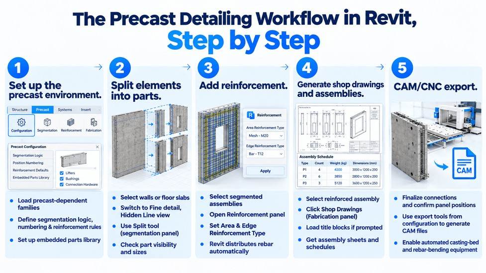
1. Set up the precast environment: Open your structural (or multi-discipline) project, go to the Precast tab, and click Configuration. This is where you load precast-dependent families and define the rules that govern everything downstream - segmentation logic, position numbering, reinforcement defaults, and the embedded parts library (lifters, bushings, connection hardware). Skipping this step is the single most common reason a precast workflow falls apart later - without configured rules, the split and reinforcement tools have nothing to reference.
2. Split elements into parts: Select your structural walls or multi-layer floor slabs, switch the view to Fine detail with a Hidden Line visual style, and use the Split tool under the segmentation panel. This divides a continuous wall or floor into discrete precast panels, sized according to whatever rules you set up in Configuration - panel weight limits, transport dimensions, casting-bed size. You can then toggle part visibility to inspect individual segments separately from the original host element, which is genuinely useful for checking nothing's been mis-sized before you move on.
3. Add reinforcement: Select the segmented assemblies, open the Reinforcement panel on the Precast tab, click Reinforcement, and finish the selection. Specify Area Reinforcement Type and Edge Reinforcement Type in the properties dialog, and Revit distributes rebar automatically based on each panel's geometry. This is a huge time saver over manually placing bars panel by panel - and it updates automatically if the panel geometry changes later, which matters a lot given how often Indian project drawings get revised mid-construction.
4. Generate shop drawings and assemblies: Select a reinforced precast assembly, click Shop Drawings under the Fabrication panel, and load your title blocks if prompted. Revit compiles assembly sheets and schedules - piece weights, counts, dimensions - and files them under Assemblies in the Project Browser. What used to take a detailer days of manual 2D drafting now comes out of the model directly, provided the LOD 400 work upstream was done properly.
5. CAM/CNC export: With connections finalised and every panel's position confirmed, use the export tools set up during configuration to generate CAM files - numerical control data that automated casting-bed and rebar-bending equipment can read directly. This is the step that actually closes the loop between digital model and physical factory floor.
Each of these steps depends entirely on the one before it. A wall you haven't split can't be reinforced with panel-level rebar. Panels without finished reinforcement won't produce meaningful shop drawings. And shop drawings that don't reflect final connection details will just generate CAM files that need reworking on the shop floor anyway - which is exactly the kind of rework a fabrication-ready model exists to prevent.
Generating Shop Drawings From a Precast Model
Worth dwelling on this bit a little longer, because it's where the ROI of the whole workflow becomes obvious. A shop drawing extracted straight from an LOD 400 model isn't drafted from scratch - it's a view of data that already exists. Dimensions, bolt lists, cut lengths, piece marks: all of it comes from the model, not from someone re-measuring a plan and typing numbers into a title block. That consistency matters enormously once a project has forty or fifty unique panel types running through a casting yard at once, which isn't unusual on a mid-size Indian residential or metro project.
It's also the point in the pipeline where mistakes get caught cheaply. A panel dimension that's wrong on a shop drawing is an annoying revision. The same error discovered after the panel's already cast and sitting on a truck is an expensive one - and on Indian sites, where transport slots and crane bookings are tightly scheduled, a late-caught error can knock an install sequence back by days, not hours.
Once the shop drawings are clean, the same model data does a second job. It's the reason how fabrication-level models feed accurate quantity takeoffs is worth understanding: concrete volumes, rebar weights, and piece counts come straight from the model instead of someone re-measuring drawings.
Also read: MEP Drawings in Construction - Types, Purpose & Complete Guide
CAM Export: How the Model Reaches the Factory Floor
CAM export is the part that non-BIM folks often find genuinely surprising the first time they see it: the same Revit model that produced your drawings can also drive the machinery that cuts, bends, and casts the physical component. Rebar-bending machines, plasma cutters, automated casting-bed setups - all of them can take numerical control data generated straight out of the model, provided the connection details and panel positions were locked down before export.
This is also where a Revit-to-fabrication handoff most often breaks if the earlier steps were rushed. If reinforcement wasn't finalised, or if a connection detail got left generic instead of fully resolved, the CAM file inherits that gap - and a shop floor discovering a missing detail mid-production is a far costlier problem than a detailer catching it on screen. A model-first discipline through every step above is really the whole game here.
Also read: Essential Revit Automation Tips to Boost Productivity
Common Mistakes in Precast BIM Detailing
A few patterns show up again and again, whether the project is in Mumbai or Manchester:
- Skipping the Configuration step. Jumping straight to splitting elements without setting segmentation rules first, which leads to inconsistent panel sizing that has to be manually corrected later.
- Treating reinforcement as an afterthought. Adding rebar after shop drawings are already partway drafted, instead of finishing reinforcement first so drawings pull complete data.
- Leaving connections generic too long. Carrying LOD 350-style generic connections into what's meant to be an LOD 400 deliverable, which produces shop drawings that look finished but aren't fabrication-ready.
- No handoff meeting between design and detailing teams. The design model gets thrown over the wall with no walkthrough, and the detailer ends up guessing at design intent instead of confirming it.
- Manual edits to extracted shop drawings. Once someone starts hand-editing a 2D view instead of fixing the 3D model, the drawing and the model drift apart - and the CAM export ends up reflecting the wrong one.
Most of these come down to one habit: treating precast detailing as a rushed final stage instead of a proper phase with its own time, its own configuration, and its own review cycle.
Where This Fits Into Indian Construction Right Now
Precast isn't a fringe technique here anymore. India's precast concrete market was valued at roughly USD 4.59 billion in 2025 and is projected to grow steadily through the next decade, and it's showing up specifically on the kind of large, repetitive-element projects India is building a lot of right now - metro rail viaducts and stations, highway flyovers under NHAI's corridor programmes, and mass affordable-housing schemes where repeatable panel types make precast genuinely cost-effective at scale.
That's also pulling more Indian BIM professionals into precast-specific detailing roles, including a fair number who end up detailing for GCC and international precast manufacturers remotely - the skillset travels well because Revit's precast toolset works the same wherever the casting yard sits. If you're coming from a general Revit structural background, this is worth knowing: precast detailing sits alongside other high-demand specialisations that Indian firms are actively hiring for right now, and LOD 400 fluency is one of the more specific, less commoditised skills you can build.
Also read: A Day in the Life of an MEP BIM Engineer in India (2026)
Coordinating a precast package properly also means it needs to sit correctly inside the broader project schedule - precast erection sequencing is exactly the kind of thing that benefits from 4D scheduling tied back to the model rather than a spreadsheet that's disconnected from what's actually been cast and delivered.
Also read: What is a BIM Engineer? Roles, Skills, Salary and Career Path 2026
Kaarwan’s BIM Certification Program for Civil Engineers covers precast and fabrication detailing alongside structural modelling and shop drawing workflows, helping you build job-ready BIM skills.
FAQs
What LOD is required for precast fabrication?
LOD 400. This is the level where every panel, connection, and embed is modelled with enough precision to generate shop drawings and CAM files directly - no generic placeholders left in the model.
What's the difference between a shop drawing and a construction drawing?
A construction drawing communicates design intent to the site team - what's being built and roughly how. A shop drawing is a manufacturing instruction - exact panel dimensions, reinforcement, bolt lists, and piece marks a factory or fabricator uses to actually produce the component.
Do all Revit projects need precast detailing?
No. It's only relevant where precast concrete or off-site fabricated elements are part of the structural system - cast-in-situ projects don't need it. But on metro, highway, and large housing projects in India, where precast is increasingly the default for repetitive elements, it's becoming a standard modelling requirement rather than a specialist add-on.
What is a Precast BIM Detailer, and what does the role pay?
A Precast BIM Detailer takes a coordinated structural model and advances it to LOD 400 - splitting elements, modelling reinforcement and connections, and producing shop drawings and CAM-ready data. Pay varies quite a bit by city, experience, and whether you're working for a domestic firm or an international precast manufacturer, but LOD 400 fabrication skills are genuinely scarce compared to general Revit modelling, which tends to put detailers with this specialisation ahead of generalist BIM modellers at comparable experience levels.