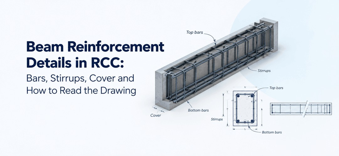
Beam reinforcement details show how steel is placed inside an RCC beam: main (tension) bars near the bottom, hanger or compression bars on top, and stirrups along the length to resist shear. Bar sizes, spacing and cover come from the structural drawing and get checked against IS 456:2000 and SP 34. This guide covers each bar type, singly vs doubly reinforced sections, the IS 456 minimum and maximum steel, stirrup spacing, and how to read a beam schedule without losing your mind.
Here's the thing about beams. Once the concrete is poured, the steel is gone for good. The drawing is the only witness. Get a bar wrong on paper (or on site) and you won't find out until a crack shows up two monsoons later.
Also : Essential RCC Construction Terminology
What are beam reinforcement details?
Concrete is great at being squeezed and terrible at being stretched. Lay a plain concrete beam across two supports, load it, and the underside stretches, cracks, and the beam goes. A reinforced concrete beam fixes that by putting steel exactly where the stretching happens.
So "beam reinforcement details" is really the full instruction set for that steel: how many bars, what diameter, where they sit, how they're bent, how far they run, how tightly the stirrups are packed. In India you'll usually see Fe 500 or Fe 500D deformed bars specified (made to IS 1786), and the stirrups are called "rings" by almost everyone on site.
If you're still fuzzy on how a slab hands its load to the beam, read about one-way and two-way slab reinforcement first. We won't repeat it here.
A quick word on codes, because they keep moving. IS 456:2000, with its amendments, is still the enforceable concrete code in India. A fifth revision (likely to be titled "Structural Concrete") is in draft. Detailing practice follows SP 34, and seismic detailing follows IS 13920. Before you quote a clause number in an exam answer or a drawing note, check the current BIS listing.
Types of bars in a beam: main, hanger, stirrups, bent-up, side face
A beam cage has three jobs: carry bending tension, hold its own shape, and resist shear. Five kinds of steel share those jobs.
| Bar type | Where it sits | What it does | Typical callout |
| Main (tension) bars | Bottom face at mid-span; top face over supports | Carry bending tension | 3-16Ø |
| Hanger / anchor bars | Top face of the beam | Hold the stirrups in place, take minor hogging | 2-12Ø |
| Stirrups (rings) | Wrapped around the longitudinal bars | Resist shear, confine the bars, keep the cage rigid | 2L-8Ø @ 150 c/c |
| Bent-up bars | Main bars cranked up at about 45° near supports | Add shear resistance, double as top steel | 1-16Ø cranked |
| Side face bars | Both faces of a deep web | Control cracking in the web | 2-10Ø each face |
Bent-up bars were once the standard answer to shear near supports. Most current drawings lean on stirrups instead, since cranked bars are fiddly to fabricate. You'll still meet them in older drawings and in textbooks, so know what they are.
Redrawing bars by hand? Kaarwan's Professional BIM Certification Program for Civil Engineers covers Structural Modelling and Rebar, Steel and Fabrication, with a skill certificate.
Singly vs doubly reinforced beam
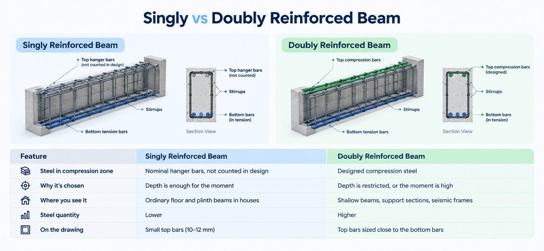
A singly reinforced beam has steel designed to work only in tension, which means the bottom bars at mid-span. The two bars sitting on top? They're there so the stirrups have something to tie to. The design doesn't count on them.
A doubly reinforced beam carries designed steel in the compression zone as well, working alongside the concrete.
Why would anyone bother? Usually because the beam can't be deep enough. Think of a beam under a low basement ceiling, or an architect who has capped the depth to keep a clean headroom line. Extra steel lets a shallower section take a bigger moment. You'll also see it at the support sections of continuous beams, and in earthquake frames where moments reverse and top and bottom bars take turns in tension.
| Feature | Singly reinforced beam | Doubly reinforced beam |
| Steel in compression zone | Nominal hanger bars, not counted in design | Designed compression steel |
| Why it's chosen | Depth is enough for the moment | Depth is restricted, or the moment is high |
| Where you see it | Ordinary floor and plinth beams in houses | Shallow beams, support sections, seismic frames |
| Steel quantity | Lower | Higher |
| On the drawing | Small top bars (10–12 mm) | Top bars sized close to the bottom bars |
Working out the moment of resistance is a separate design topic, so I'm leaving it out.
Minimum and maximum reinforcement in a beam, IS 456:2000
The code sets guardrails at both ends. Too little steel, and the beam cracks and fails with almost no warning. Too much, and the concrete crushes before the steel yields, which is a brittle failure. The aim is an under-reinforced beam: steel yields first, and you get wide cracks and visible sag before anything lets go.
Here, b is width, d is effective depth, D is overall depth and fy is the steel's yield strength.
| IS 456 clause | Rule | In plain numbers |
| 26.5.1.1(a) | Minimum tension steel: As/bd ≥ 0.85/fy | Fe 415: about 0.205% of bd. Fe 500: 0.17% |
| 26.5.1.1(b) | Maximum tension steel: 0.04 bD | 4% of the gross section |
| 26.5.1.2 | Maximum compression steel: 0.04 bD | 4% of the gross section |
| 26.5.1.3 | Side face steel when web depth exceeds 750 mm | 0.1% of web area, split between both faces, spaced at no more than 300 mm or the web thickness, whichever is less |
| 26.5.1.5 | Maximum stirrup spacing | 0.75d for vertical stirrups, d for 45° inclined, never more than 300 mm |
| 26.5.1.6 | Minimum shear steel: Asv/(b·sv) ≥ 0.4/(0.87 fy) | Every beam gets stirrups, even a lightly loaded one |
| 26.3.2 | Minimum gap between parallel bars | Greater of bar diameter or (aggregate size + 5 mm). With 20 mm aggregate, that's 25 mm |
| 26.4, Table 16 | Nominal cover by exposure | Mild 20, moderate 30, severe 45, very severe 50, extreme 75 mm, and never less than the bar diameter |
Try it on a 230 × 450 mm beam (the usual width to sit flush with a 9-inch wall), with d ≈ 405 mm in Fe 500. Minimum steel comes to about 0.17% × 230 × 405 ≈ 158 mm². Two 12 mm bars already give 226 mm². The maximum, 4% of 230 × 450, is about 4,140 mm², roughly twenty 16 mm bars. Good luck fitting twenty bars into a 230 mm width. In practice, bar congestion stops you long before the code does.
Stirrup spacing and shear reinforcement
Shear is the sneaky one. It doesn't announce itself with a sag. It shows up as diagonal cracks near the supports, at roughly 45°. Stirrups stitch across those cracks. That's why shear reinforcement in beams is packed tight near the columns, where shear peaks, and relaxed toward mid-span.
A typical callout reads 2L-8Ø @ 100 c/c near the supports and 2L-8Ø @ 150 c/c through the middle. "2L" means two-legged, and c/c is centre to centre.
IS 456 caps the spacing at 0.75d or 300 mm. For our 230 × 450 beam, 0.75d is about 304 mm, so the 300 mm cap governs. Most house drawings sit well below that. The first stirrup usually starts around 50 mm from the column face, which is common practice rather than a code number.
In earthquake-resisting frames, IS 13920 tightens things further. Over a length of about 2d from the column face, where plastic hinges form, the stirrups become closed hoops at much closer spacing. The spacing is governed by d/4 and a multiple of the smallest bar diameter, and it often works out near 100 mm. Hoop ends carry 135° hooks, not 90°. Reason: when shaking spalls the cover, a 90° hook can spring open, while a 135° hook tucks its tail into the core and stays put.
Side face reinforcement in deep beams
When the web gets deep (over 750 mm), cracks can open up along the sides, in the zone between the top and bottom steel. Side face reinforcement in a beam is the extra longitudinal steel that keeps those cracks fine.
Quick example: a 300 × 900 mm beam. Web area is 300 × 900 = 270,000 mm², and 0.1% of that is 270 mm². Split across two faces, that's 135 mm² each, so two 10 mm bars (157 mm²) per face does the job. You'll see this in deep transfer girders and podium or parking-level beams, rarely in a regular house.
Cantilever and continuous beams: where the steel changes
Cantilever beam reinforcement. A cantilever bends the opposite way from a simply supported beam. The tension is on top, so the main steel moves to the top and has to run well back into the support. The classic site mistake is stopping those bars at the wall face because the balcony "ends there". It doesn't. The anchorage into the backspan is what holds the balcony up. There's more on cantilever detailing in our balcony guide. Stirrups sit closest near the root, where shear and moment both peak.
Continuous beams. Here the steel plays musical chairs. Bottom steel carries mid-span, top steel takes over at the supports, and neither runs full length at full strength. IS 456 clause 26.2.3 governs the curtailment. At least a quarter of the bottom bars in a continuous beam run straight into the support, and at least a third of the support's top steel carries on beyond the point of inflection by the greatest of d, 12 bar diameters or one-sixteenth of the clear span. Your drawing will show this as top bars of different lengths, marked with cut-off points.
Cover, anchorage and laps in a beam
Cover. Many house drawings default to 25 mm for beams. That clears the 20 mm mild-exposure value in Table 16, but only just, and it falls short for moderate exposure, where Table 16 asks for 30 mm. Concrete exposed to a coastal environment counts as severe, which is 45 mm. So a beam on the Mumbai, Chennai or Kochi coast shouldn't be copying a Pune drawing. Cover blocks do the actual work on site. If you see bars resting straight on the shuttering, stop the pour. That steel will rust and spall.
Anchorage. Bars need to be gripped by the concrete before they're allowed to end. For deformed bars in M20 concrete, development length works out to roughly 47 times the bar diameter for Fe 415 and about 57 times for Fe 500. A 16 mm Fe 500 bar, then, needs around 900 mm. Hooks help: a 90° bend counts as 8 diameters of anchorage, and a 180° hook counts as 16.
Laps. Keep them out of high-stress zones. Bottom bars lap near the supports, top bars lap near mid-span, and laps get staggered rather than stacked in one section. We'll cover lap lengths in their own guide.
Beam-column junction detailing as per IS code
Beam-column junction detailing ensures that reinforcement is properly anchored and confined to maintain structural strength and improve earthquake resistance.
The junction is where beam reinforcement gets crowded, and where earthquakes do their worst. Beam bars run through the column core, and bars at an external column end with a bend inside the column cage. Hoops continue through the joint, closer than elsewhere in seismic frames.
India's current rulebook for earthquake loads is IS 1893 (Part 1):2016, with four zones (II to V). Roughly 59% of the country's land area falls in moderate to severe hazard. BIS notified a 2025 revision that added a Zone VI, then withdrew it by gazette notification on 3 March 2026, so the 2016 edition is back in force. Design and detail to IS 1893:2016 with IS 13920:2016, and check which clauses apply to your zone and building category.
How to read a beam reinforcement drawing
Take this made-up beam. It's for reading practice, not for building.
B1 (230 × 450): Bottom 3-16Ø. Top 2-12Ø, plus 2-16Ø extra at supports. Stirrups 2L-8Ø @ 100 c/c for 900 mm at each end, 150 c/c elsewhere. Cover 25 mm clear.
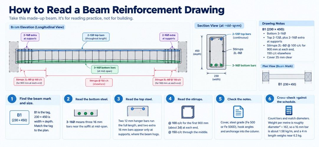
- Find the beam mark and size. B1 is the tag, 230 × 450 is width × depth. Match the tag to the plan.
- Read the bottom steel. 3-16Ø means three 16 mm bars near the soffit at mid-span.
- Read the top steel. Two 12 mm hanger bars run the full length, and two extra 16 mm bars appear only at supports, where the beam hogs.
- Read the stirrups. @ 100 c/c for the first 900 mm (about 2d) at each end, @ 150 c/c through the middle.
- Check the notes. Cover, steel grade (Fe 500 or Fe 500D), hook angles and anchorage into the column.
- Cross-check against the schedule. Count bars and match diameters. Weight per metre is roughly diameter² ÷ 162, so a 16 mm bar is about 1.58 kg/m, and a 4 m length weighs near 6.3 kg. Handy when the steel truck arrives.
Also Read :
Essential RCC Construction Terminology
Want to see this steel inside a live model? Ready to model this steel in Revit? Kaarwan's Professional BIM Certification Program for Civil Engineers covers RCC beam modelling and rebar detailing, week by week.
Modelling beam reinforcement in Revit
Reading beam steel on paper is one skill. Modelling it is another, and it shows you things 2D drawings hide. In Revit you place stirrup sets with set spacing, assign cover per element and tag bars with callouts. Schedules then update from the model, so quantities don't drift away from the drawing. You also see the beam-column junction in 3D, and congested bars suddenly look very real.
Structural Modelling (RCC) in the Professional BIM Certification Program for Civil Engineers covers columns, beams, slabs and foundations in Weeks 3 to 4, and Rebar, Steel and Fabrication follows in Weeks 5 to 6. If you're heading toward prefab work, precast detailing is the natural next read. Our free Architect's Toolkit is worth a look too.
FAQs
What is a singly reinforced beam?
A beam with designed steel only in the tension zone, usually the bottom at mid-span. Any bars on top are nominal, there to hold the stirrups.
Why is a doubly reinforced beam provided?
When depth is restricted or the moment is high. Steel in the compression zone helps a shallower section carry more load. It's also common at support sections and in seismic frames.
When is side face reinforcement provided in a beam?
When the web depth exceeds 750 mm. IS 456 asks for 0.1% of web area, split equally between both faces, at no more than 300 mm spacing or the web thickness.
What is shear reinforcement in beams?
Mostly vertical stirrups (sometimes bent-up bars) that resist diagonal tension near supports. They're packed closer at the ends and spread out toward mid-span.
How to read a beam reinforcement drawing?
Find the beam mark and size, read bottom and top bar callouts, then the stirrup spacing, then the notes on cover, hooks and anchorage. Cross-check against the bar bending schedule.
How to reinforce a beam?
Fix bottom main bars, top hanger bars and stirrups to the drawing, maintain cover with blocks, anchor bars into the columns, and lap away from peak-stress zones.
What is an under-reinforced beam?
One where steel yields before the concrete crushes. It fails gradually, with visible cracking and deflection, which is why codes aim for it.