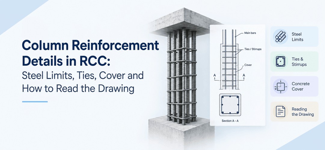
Column reinforcement details tell you exactly what steel sits inside an RCC column: how many vertical bars, how thick they are, how the lateral ties wrap them, how much concrete cover protects them, and where the bars lap. IS 456:2000 sets the limits (0.8 to 6 percent steel, a minimum of four bars in a rectangular column, 12 mm minimum bar diameter), and IS 13920 pulls the ties closer near joints for earthquake zones.
This guide walks through each rule step by step, works one G+2 example, and shows you how to read a column schedule without squinting.
Why does this deserve your attention in India in particular? About 59% of India's landmass is considered earthquake-prone under IS 1893 (Part 1):2016. A newer 2025 version with a brand-new Zone VI was released, but BIS withdrew it through a gazette notification on 3 March 2026, so the 2016 map is still what your drawings follow. The column is where a building either bends gracefully or doesn't. If a term below is new to you, the RCC terms explained page is a quick catch-up.
What are column reinforcement details?
They are the steel instructions for one column: bar count and diameter, tie diameter and spacing, cover, lap location and the shape of the cage in section. On a drawing they show up as a column mark like C1, a size, a bar callout and a tie callout.
Think of a column as a tall concrete pillar with a steel skeleton inside. The vertical bars carry load and resist bending from wind and quakes. The ties keep those bars from buckling outward. Get either wrong and the column loses what the steel was there to provide.
Most Indian site engineers meet these details first as a column schedule on the structural sheet. We'll get to reading it shortly. First, the parts.
Main bars and ties: what does each do?
Main bars (longitudinal bars) take compression and bending. Ties (lateral ties, or stirrups in site talk) hold those bars in position, stop them buckling and confine the concrete core. That's the core of RCC column reinforcement. Spirals are a third option, and they're covered further down.
| Part | What it is | Job on site | Common size in Indian buildings |
| Main (vertical) bars | Ribbed TMT bars, usually Fe 500D or Fe 550D | Carry load, resist bending | 12 mm minimum; 16, 20, 25 mm common |
| Lateral ties | Closed loops around the main bars | Stop buckling, hold bars in place, confine concrete | 8 mm is the usual site choice |
| Cross-ties | Extra ties across the section | Support bars that sit far from a tie corner | Same as the ties |
| Spiral (helical) | Continuous coil instead of separate ties | Better confinement, mostly circular columns | 8 to 10 mm |
Want to model columns and rebar in Revit? Kaarwan's BIM Certification Program for Civil Engineers teaches Structural Modelling (RCC) and Rebar, Steel and Fabrication hands-on.
What is the minimum and maximum steel in an RCC column as per IS 456?
Clause 26.5.3.1 of IS 456:2000 sets the minimum reinforcement in a column at 0.8% of the gross cross-sectional area, and the maximum reinforcement in a column at 6%. Where bars from the column below lap with the bars above, steel should usually stay within 4%.
Take a 300 × 450 mm column. Gross area is 135,000 mm². So:
- 0.8% = 1,080 mm² (the floor)
- 4% = 5,400 mm² (the practical ceiling at laps)
- 6% = 8,100 mm² (the code ceiling)
The rest of the clause matters just as much. Minimum four bars in a rectangular column, six in a circular one, nothing under 12 mm, and spacing along the perimeter not over 300 mm.
Here's the thing nobody says out loud: 6% looks fine on paper and is a nightmare on site. Try pushing a needle vibrator through a cage that's 6% steel and lapping. Concrete honeycombs, and honeycombing at a joint is a bad day. That's why most real column schedules in Indian houses sit between roughly 1% and 3%.
What is the tie (stirrup) spacing and diameter in a column?
Under IS 456 clause 26.5.3.2, column ties spacing (the pitch) must not exceed the least of three things: the column's least lateral dimension, 16 times the smallest longitudinal bar diameter, or 300 mm.
Tie diameter must be at least one-fourth of the largest main bar, and never under 6 mm. This is the rule behind column stirrups spacing on every drawing.
Run it on the same 300 × 450 column with 20 mm bars:
- Least lateral dimension: 300 mm
- 16 × 20 mm = 320 mm
- Hard cap: 300 mm
The answer is 300 mm. With 16 mm bars, 16 × 16 = 256 mm takes over instead. On the tie diameter, ¼ × 20 = 5 mm, so the 6 mm floor applies. Most sites still go with 8 mm because it's stiffer to bind and won't sag.
One more catch. A tie only supports the bars at its corners. A bar sitting far from any corner (the code works with roughly 75 mm) needs a cross-tie, or it can bow out under load. Hooks matter too, and IS 13920 wants 135° hooks turned into the core, not lazy 90° ones.
Also read: Lap length of bars: what it is, IS 456 values and how to use it on site
What cover is needed for column bars?
IS 456 clause 26.4.2.1 keeps nominal cover for longitudinal bars in a column at 40 mm or the bar diameter, whichever is bigger. Small columns (side 200 mm or less, bars up to 12 mm) may use 25 mm. Fire rating and exposure can push the number up.
A quick word on where you measure from. The code talks about cover to the reinforcement. Plenty of Indian project specs state 40 mm to the ties. Both exist in real drawings, so read the general notes on your sheet before you set the cover blocks. Don't guess.
And the cover blocks themselves? Use proper ones. Cement or plastic spacers, tied on all four faces. Brick chips and stray stones aren't cover blocks, even if they've been "working fine" for years.
Where are laps allowed in a column?
Laps belong in the middle portion of a column's height, away from the ends, where moment and confinement demand are highest. Stagger them so you don't splice every bar in one plane. On the drawing, the lap location is shown in the elevation.
Now the lap length itself. On Indian sites you'll hear "50d" shouted constantly, so a 20 mm bar laps 1,000 mm. That's a rule of thumb. The real figure comes from development length, which depends on the bar's grade, the concrete grade and whether the bar is in tension or compression. Whatever your drawing states, use that. We've broken the whole thing down in the lap length guide.
Convenience is the enemy here. Everyone wants to lap right above the slab because it's easy to reach. That puts every splice at the weakest, most stressed spot. Check your drawing.
Closer ties at column ends: seismic detailing (IS 13920)
IS 13920 asks for special confining reinforcement at both ends of every column, over a length (Lo) equal to the largest of the column's bigger lateral dimension, one-sixth of the clear height, or 450 mm. Within that length, ties go in at no more than a quarter of the least dimension, six times the smallest bar diameter, or 100 mm, whichever is least. Outside it, the looser IS 456 spacing is fine.
Why the extra effort? When a quake shakes a frame, the hinges form at the column ends. Closer ties hold the concrete core together so the column keeps carrying load as it deforms, instead of snapping. The 2001 Bhuj earthquake taught Indian engineers this lesson expensively: many reinforced concrete frame buildings suffered badly where ties were thin and widely spaced.
Don't skip ties through the beam-column joint either. It's congested. It's annoying. It still needs them. For how the beam side of that joint is detailed, see our guide on beam reinforcement details.
Also read: Types of footings
Worked example: column reinforcement for a G+2 residential building (illustrative, not a design)
Say a G+2 house has a column marked C1. Column size and reinforcement for a G+2 vary with loads, soil and seismic zone. The structural engineer fixes the numbers. This example only shows how the rules above fit together.
Illustrative, not a design. Always build from your engineer's stamped drawings.
Take C1 as 300 × 450 mm with 6 bars of 20 mm (4 at the corners, 1 in the middle of each long face) and 8 mm ties.
- Steel area: 6 × 314 mm² ≈ 1,885 mm², which is about 1.4% of 135,000 mm². Comfortably between 0.8% and 4%.
- Steel weight: 20² ÷ 162 ≈ 2.47 kg per metre per bar, so about 14.8 kg of main steel per metre of column.
- Tie diameter: 8 mm clears the minimum (6 mm).
- General pitch: the code cap works out to 300 mm. The schedule may specify 150 mm c/c through the middle height.
- End zones: assume 3 m floor-to-floor with a 450 mm beam, so clear height is about 2.55 m. One-sixth of that is 425 mm. Lo is the largest of 450, 425 and 450 mm, which gives 450 mm. Spacing there is the least of 75, 120 and 100 mm, so 75 mm c/c.
- Cross-tie: the two middle bars on the long faces sit well over 75 mm from a corner, so add one cross-tie with 135° hooks.
- Cover: 40 mm.
Written the way a drawing would show it: C1 | 300 × 450 | 6-Ø20 | Ø8 @ 150 c/c | Ø8 @ 75 c/c for 450 mm at both ends.
How to read a column reinforcement drawing
Reading a column reinforcement drawing is a short, repeatable routine. Start at the schedule, confirm the size, decode the bars and ties, then check the zones, the section and the notes.
- Find the column mark (C1, C2) and the storey it applies to.
- Read the size, for example 300 × 450. The first number is usually the width as drawn on the grid, so check the orientation.
- Decode the main bars. "6-Ø20" means six bars, 20 mm diameter. If two sizes are mixed, they'll be listed separately.
- Decode the ties. "Ø8 @ 150 c/c" means 8 mm ties, 150 mm centre to centre.
- Look for zone notes. A closer spacing at the ends (like 75 mm for 450 mm) is the seismic confining zone.
- Open Section A-A. It shows where each bar sits and how the ties and cross-ties wrap them.
- Check the elevation. Lap positions, stagger and joint ties live here.
- Read the general notes for cover, steel grade and hook details.
If your drawing and the schedule disagree, don't pick a winner. Stop and ask the engineer.
Modelling column rebar in Revit
In Revit, you host rebar on the column and control cover, bar shape and layout.
Create one rebar set for the end confining zones and another for the middle, and the model carries the same spacing logic the drawing does. Schedules then pull counts and lengths straight from it.
This matters more than it sounds. A modelled cage shows clashes at the beam-column joint before they reach site. Our guide on how reinforcement is modelled for fabrication shows how that flows into bar bending schedules, and the structural BIM modeler role page explains who does this work and what they're paid to catch.
If you want to learn it hands-on, the Professional BIM Certification Program for Civil Engineers covers exactly that: Structural Modelling (RCC) and Rebar, Steel and Fabrication.
Common site mistakes (checklist)
Run through these before the shutter closes. Most column failures start as something on this list.
- Cover blocks missing or wrong, with the cage leaning on the shuttering
- Ties at 90° hooks instead of 135°
- Ties skipped inside the beam-column joint
- All laps in one plane, or right at the slab level
- Tie spacing "averaged" instead of measured zone by zone
- Bars off-plumb or twisted from the starter bars
- Congestion so bad the vibrator can't get in
- Rusty or unmarked bars, with grade and heat number not checked
- Drawing revision on site is not the current one
Drawings are only half the job. Kaarwan's civil BIM program takes you from reading column schedules to modelling them in Revit. Download the syllabus.
FAQs
What is the minimum reinforcement in a column?
IS 456:2000 clause 26.5.3.1 sets it at 0.8% of the gross cross-sectional area of the column. You also need at least four bars in a rectangular column (six in a circular one), each at least 12 mm in diameter.
What is the maximum reinforcement in a column?
6% of the gross cross-sectional area under IS 456. Where bars lap, steel should usually stay within 4%, and real columns in houses are mostly detailed well below either figure so concrete can be compacted.
What is the spacing of stirrups in a column?
The tie pitch must not exceed the least of the column's least lateral dimension, 16 times the smallest main bar diameter, or 300 mm. In seismic zones, IS 13920 tightens this to as little as 75 to 100 mm near the column ends.
What is the difference between a tied and a spiral column?
A tied column uses separate closed ties. A spiral column uses a continuous helical coil, which confines the core better. A helical column needs at least six longitudinal bars, and the helical pitch is capped at 75 mm and one-sixth of the core diameter.
What cover is required for a column?
Nominal cover for column bars is 40 mm or the bar diameter, whichever is greater, with 25 mm allowed for small columns carrying bars up to 12 mm. Your project's drawing notes and fire rating can ask for more.