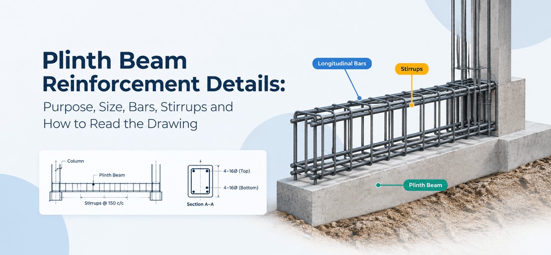
Plinth beam reinforcement is a cage of main bars (top and bottom) and stirrups, sitting inside an RCC beam cast at plinth level and anchored into every column. The beam ties the columns together and carries wall load down to the footings. This guide covers why it's there, how it differs from a tie beam and a plinth band, the bars and stirrups you'll usually see, typical sizes, anchorage at columns, and how to read the drawing without guessing.
One warning before we start. Every number below is typical, not a design. Your structural drawing always wins.
Also Read: Types of Footings in Construction
What is a plinth beam?
A plinth beam is an RCC beam cast at plinth level, between the foundation and the superstructure, running along the column lines and under the walls. In India the plinth is normally kept at least 450 mm above the surrounding ground, per BIS guidance. The beam sits at the top of that zone.
It's also the member that vanishes under flooring and plaster. That's exactly why mistakes in it survive for years.
Why is a plinth beam provided?
A plinth beam does three jobs: it ties the columns, carries the walls above, and forms part of the earthquake load path.
Footings never settle by the same amount. Soil changes across a plot, and loads differ column to column. Without a tie, one column drops a little more than its neighbour and the wall between them cracks diagonally. With a plinth beam, moving one column means bending a beam, so the footings behave more like one system.
The seismic part matters in India. Roughly 59% of the country's land falls in seismic zones III to V under IS 1893 (Part 1):2016. The 2001 Bhuj earthquake (M7.7) killed around 20,000 people. Sites in zones III to V are where ductile detailing from IS 13920 gets serious, and the plinth beam is one of the cheapest places to get it right.
Plinth beam vs plinth band vs tie beam vs grade beam
These four get mixed up constantly. The same member can legitimately carry two names.
| Term | Where it's used | What defines it |
| Plinth beam | RCC framed buildings | Designed beam at plinth level, bars and stirrups from the drawing |
| Plinth band | Load-bearing masonry (IS 4326) | Slim RC band; IS 4326 minimum is 75 mm thick, 2 bars of 8 mm, 6 mm links at 150 mm |
| Tie beam | Any level | Named by function: it ties columns or footings together |
| Grade / ground beam | At or below ground level | Spans between footings or piles, often carries walls over weak soil |
A plinth band is mainly there when uneven foundation settlement is the worry, and it makes walls act as one box. A plinth beam in a frame is a proper flexural member. Don't copy band steel into a frame beam. Read the mark on the drawing (PB1, GB2, TB1) and go with that.
Want to model plinth beams, bars and stirrups instead of only reading them? Kaarwan's Civil BIM course covers RCC Structural Modelling in Weeks 3–4.
What are the plinth beam reinforcement details?
Plinth beam reinforcement is longitudinal bars at top and bottom, held by closed stirrups, with specified cover. Here's what residential drawings usually show:
| Element | Typical residential (illustrative) | Job |
| Bottom bars | 2 to 3 nos, 12 to 16 mm (up to 20 mm on long spans) | Resist sagging tension |
| Top bars | 2 to 3 nos, 10 to 16 mm | Resist hogging near supports, hold stirrups |
| Extra top bars | Near supports, about L/4 | Pick up support moment |
| Stirrups | 8 mm at 100 mm c/c near columns, 150 mm at mid-span | Shear and confinement |
| Steel grade | Fe 500D (IS 1786) | Ductility |
| Concrete | M20 minimum, M25 common | Strength and durability |
| Clear cover | 25 to 40 mm | Corrosion protection |
Now the code checks that sit behind those numbers.
Minimum steel. IS 456 sets minimum tension steel at 0.85bd/fy. Take a 230 × 300 mm beam with Fe 500, 25 mm cover and 8 mm stirrups, so d is about 261 mm. That works out to roughly 102 mm², and two 12 mm bars give about 226 mm². So the minimum is easy to clear. It's a floor, not a design.
Stirrup spacing. IS 456 caps vertical stirrups at 0.75d or 300 mm, whichever is less. For that same section, 0.75d is about 195 mm. A "200 c/c throughout" habit already breaks the limit, which is why 150 mm at mid-span is the safer pattern.
Seismic zones III to V. IS 13920 asks for at least two 12 mm bars continuous at top and bottom. It also asks for closely spaced hoops within 2d of the column face, capped at 100 mm c/c, with the first hoop right near the face (about 50 mm). Hoops get 135° hooks, not 90°, so they don't spring open under cyclic loading.
Cover. IS 456 Table 16 gives 20 mm nominal cover for beams in mild exposure and 30 mm for moderate. Plinth beams cast against or near soil are usually detailed with more, and 40 mm is common. Use whatever the drawing notes say.
What is the size of a plinth beam?
There's no universal size. Width usually matches the wall above, so a 230 mm brick wall gets a 230 mm wide beam. Depth follows span and load.
| Building | Typical size (mm) | Typical bars |
| Single storey, short spans | 230 × 230 | 4 nos, 12 mm |
| G+1, ordinary spans | 230 × 300 | 4 to 6 nos, 12 mm |
| G+2, spans to about 4.5 m | 230 × 380 | 6 nos, 12 to 16 mm |
| Long spans or heavy walls | 300 × 450 | Designed |
Treat the table as typical values, not a design. IS 13920 also expects a seismic-frame beam to be at least 200 mm wide with a width-to-depth ratio above 0.3, which 230 × 300 clears comfortably.
One detail to catch on the drawing instead of on site: a 150 mm beam under a 230 mm wall leaves part of the wall hanging over nothing.
How are plinth beam bars anchored at columns and corners?
Plinth beam bars are anchored by extending them into the column core and bending them if the column is too small to hold the full development length.
Do the sum. For Fe 500 bars in M20 concrete, IS 456 development length in tension works out to about 57 times the bar diameter. A 12 mm bar needs roughly 680 mm and a 16 mm bar roughly 910 mm. A 230 or 300 mm column can't hold that straight, so the bars bend into the core. IS 456 gives a 90° bend an anchorage value of 8 times the bar diameter.
At corners, bars arriving from both directions fight for the same space inside the column cage. Keep the bent ends inside the column ties, top bars bending down and bottom bars bending up, and sort out congestion at the drawing stage. Understanding column reinforcement details, including tie spacing, cover and bar placement, also helps you check how the beam reinforcement fits within the column cage. Hacking bars to fit on site is how anchorage quietly disappears.
Laps need the same care. Keep them out of the joint and out of the first 2d from the column face, and tighten the stirrups at the lap. Our guide to lap length shows the IS 456 values you'll need.
How to read a plinth beam reinforcement drawing
You read a plinth beam drawing in five moves: plan, schedule, symbols, section, notes.
Here's an invented schedule row (illustrative only, not a design):
| Mark | Size | Top | Bottom | Stirrups | Cover |
| PB1 | 230 × 300 | 2-12Ø + 1-12Ø extra at supports | 3-12Ø | 8Ø @ 100 c/c (L/4 ends), 8Ø @ 150 c/c (mid) | 40 mm |
- Find the mark on the plan. Beams are labelled PB1, PB2 and so on, along grid lines like A-B or 1-2.
- Match it in the schedule. The schedule gives width × depth, top bars, bottom bars, extra bars and stirrup spacing for that mark.
- Decode the symbols. "3-12Ø" means three 12 mm bars. Ø, T, Y or # all point to deformed high-strength bars, so "12T" is a 12 mm bar. "@ 150 c/c" means centre-to-centre spacing of 150 mm.
- Check the section cut. It shows how many bars sit where, whether bars sit in one tier or two, and what the cover looks like.
- Read the notes. Concrete grade, steel grade, cover, hook angle and lap rules live here. People skip them, and then wonder why the beam doesn't match the intent.
Never copy steel from the neighbouring beam because the dimensions look the same. If you want to go beyond reading these and model them, the Civil BIM course walks through RCC detailing inside Revit.
Also Read : Beam Reinforcement Details in RCC
Plinth beam in a bar bending schedule
The drawing tells you what goes in. The bar bending schedule tells you how much to cut.
Take PB1 above. With 40 mm cover, the stirrup's inner size is 150 × 220 mm, so about 740 mm of perimeter before hook allowances. On a 4 m span, 100 mm c/c over each end quarter and 150 mm over the middle works out to roughly 33 stirrups. A 12 mm bar weighs about 0.89 kg per metre (d²/162), which is how steel quantity comes out of the schedule. For the full method, see our guide.
Also Read : Bar Bending Schedule (BBS) guide
Common site mistakes (checklist)
- Stirrups at one spacing end to end, with no tightening near columns
- 90° stirrup hooks in a seismic zone
- No cover blocks, so bars sit straight on the PCC or the shuttering
- Beam bars cut short instead of bent into the column
- Laps placed at the column face
- Beam cast on loose backfill with no compaction
- Plumbing sleeves forgotten, then cored through the cage after the pour
- A different bar diameter swapped in "because it's available", with no engineer's sign-off
Download the syllabus to see how Kaarwan's Civil BIM course takes you from beam detailing and bar schedules to site-ready RCC models.
FAQs
What is the reinforcement in a plinth beam?
Longitudinal bars at top and bottom, typically 2 to 3 each at 12 to 16 mm, plus closed stirrups, usually 8 mm, spaced tighter near the columns. The drawing fixes the exact diameters, spacing and cover.
What is the size of a plinth beam in a house?
A 230 mm width that matches the wall is common, with a depth of 230 to 300 mm for typical G+1 homes. Long spans, heavy walls and seismic requirements push this up, so the structural drawing decides.
Plinth beam vs plinth band: what's the difference?
A plinth beam is a designed RCC beam in a framed building. A plinth band is a slim reinforced band in load-bearing masonry, with an IS 4326 minimum of 75 mm thickness and two 8 mm bars. The band ties walls into a box, and the beam carries and ties a frame.
Is a plinth beam necessary?
In RCC framed buildings it's standard practice and normally part of the design. In load-bearing masonry, IS 4326 expects plinth bands where settlement is a concern. Skipping either tends to show up later as cracked walls.
Where do the plinth beam bars end at the column?
They continue into the column core and bend if the column can't hold the full development length. For Fe 500 in M20, development length in tension is about 57 times the bar diameter.