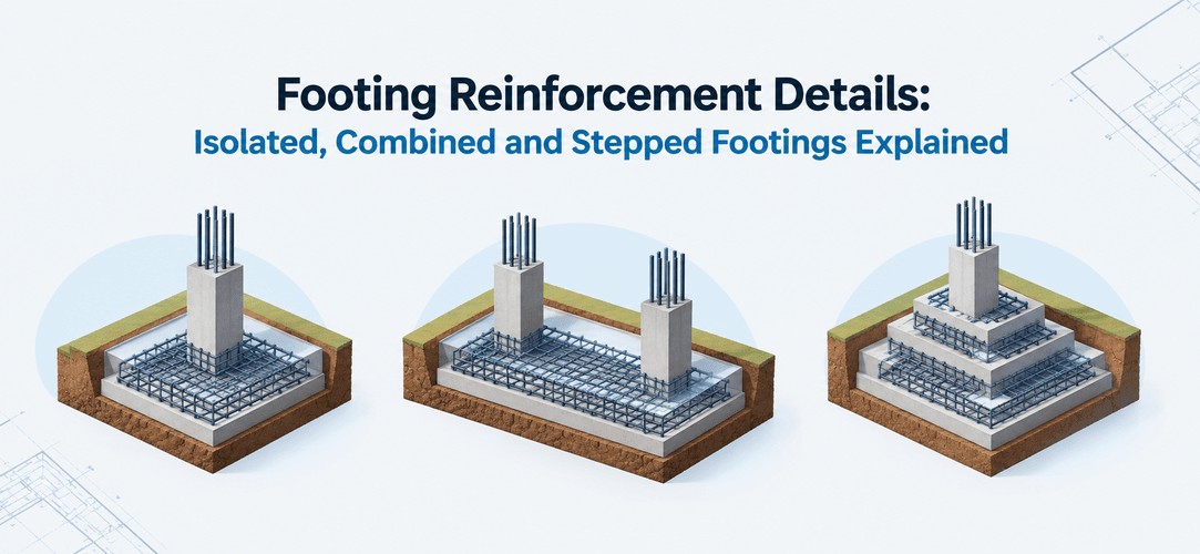
Footing reinforcement details show how steel is placed in a footing so it spreads the column load safely into the soil: a bottom mesh in both directions, starter bars for the column, and cover on the earth face. IS 456:2000 gives the rules for cover, minimum steel and development length. This guide covers isolated, combined and stepped footings, shows you how to read a footing drawing, and lists the mistakes we keep seeing on site.
One thing before we start. Which footing suits your plot is a separate question, and we've already covered it in our guide on types of footings in construction. Here we're only looking at the steel inside.
What are footing reinforcement details?
They're the part of a structural drawing that tells the bar fixer exactly what steel goes where. Bar diameter, spacing, bends, cover and the starter bars sticking out of the top all live in that one drawing.
Why does a footing need steel at all? Concrete handles compression well and tension badly. The soil pushes up on the footing, the column pushes down, and the slab bends in between. Tension builds on the underside, so that's where the main steel goes.
In India this isn't a textbook worry. About 59% of the country's land falls in seismic zones III to V, according to a 2024 Rajya Sabha reply from the Ministry of Earth Sciences, and zones IV and V together cover roughly 29%. A footing that's under-reinforced or badly anchored is a real risk in those areas.
How is an isolated footing reinforced?
An isolated footing is reinforced with a two-way mesh of bars near the bottom, with the column's starter bars standing on top of that mesh. The mesh is the main steel, because soil pressure bends the pad upward at its edges.
On a typical house job you'll see 10 mm to 16 mm bars at roughly 100 to 200 mm centres each way. That's just the range drawings commonly show. Your actual numbers come from the structural design.
Here's an illustrative example. Say a footing is 1.5 m by 1.5 m with 50 mm cover on every side. That leaves 1,400 mm of clear width, so at 150 mm spacing you fix roughly ten bars each way. Illustrative only, not a design.
One habit worth building: the bars in one direction go down first, and the other direction sits on top of them. The bottom layer does the heaviest work, so check the drawing to see which direction it is.
Turn footing drawings into Revit models. Kaarwan's BIM Certification Program for Civil Engineers covers RCC structural modelling and foundations in Weeks 3 to 4.
How is a combined footing reinforced?
A combined footing carries two or more columns on one slab, so it behaves like an upside-down beam in the long direction. Steel runs along the length, with cross bars under each column.
- Long direction, bottom: main bars under the columns and in the projecting ends, where the slab bends downward.
- Long direction, top: between the two columns the soil pushes up and the slab bends the other way. That's why you'll see top steel there, and it's the one people forget.
- Cross direction: transverse bars under each column band, spread over the width the drawing shows.
- Stirrups or shear links: often provided near the columns where shear is highest, but only if the design calls for them.
So what's the difference between isolated and combined footing reinforcement? An isolated footing has bottom steel only, in two directions. A combined footing has bottom steel along its length, plus top steel between the columns.
How is a stepped or sloped footing reinforced?
In a stepped footing, the main bottom mesh runs across the full base, which is the widest and lowest step. The upper steps sit on top, and the column starter bars pass through them down to the mesh.
What matters most is how it's cast. Pour it monolithically, with no cold joint between steps, because a cold joint is a weak plane right where you need strength. Vibrate it well too. Honeycombing at a step corner is easy to miss once the shuttering comes off.
A sloped footing follows the same logic. The mesh stays at the bottom and only the top surface slopes. IS 456 asks for a minimum thickness of 150 mm at the edge of a footing on soil (Cl. 34.1.2), so make sure the slope doesn't thin the edge below that.
What are column starter bars and how are they placed?
Starter bars, also called dowels, are the vertical bars that rise from the footing into the column. They carry the column load down into the footing, so they have to be anchored properly.
- They sit on the bottom mesh, with the bent foot resting on it. Bar lengths and bend sizes come from the drawing.
- A few ties hold them in position through the footing depth, so they don't shift while the concrete goes in.
- IS 456 Cl. 34.4.3 asks for starter bars or dowels of at least 0.5% of the column's cross-sectional area, with a minimum of four bars. Where dowels are used, their diameter shouldn't exceed the column bar diameter by more than 3 mm.
- They should rise above the footing by at least the lap length, so the column bars can lap onto them. Our lap length guide has the numbers.
Most of the time the designer simply continues the column bars down into the footing. Either way, the drawing decides.
What cover is needed for footing steel?
IS 456:2000 (Cl. 26.4.2.2) sets a minimum cover of 50 mm for footings. That's more than beams or columns get, because a footing spends its whole life against wet soil.
On Indian sites this matters more than it sounds. Footings sit through monsoon after monsoon, and in coastal cities like Mumbai, Chennai and Kochi the groundwater can be salty. Many drawings ask for more than 50 mm if the soil report flags sulphates or chlorides, or if there's no PCC bed under the footing. Follow whatever your drawing says.
A PCC (plain cement concrete) bed is usually laid first, and the steel is fixed on top of it with cover blocks. Skip the blocks and the mesh settles straight onto the PCC. That's your cover gone.
What are the minimum steel and spacing rules in IS 456?
These are the numbers a site engineer should know by heart:
- Minimum steel: footings follow the nominal steel for solid slabs (Cl. 34.5), which is 0.12% of gross area for HYSD bars like Fe415 and Fe500, and 0.15% for mild steel.
- Maximum spacing: three times the effective depth or 300 mm, whichever is smaller.
- Minimum edge thickness: 150 mm on soil and 300 mm on piles (Cl. 34.1.2).
- Rectangular footings: the short-direction steel isn't spread evenly. A higher share is concentrated in a central band under the column (Cl. 34.3), and the drawing marks that band.
- Bar size: many offices don't go below 10 mm for main bars in a footing. That's practice, not a clause.
Anchorage of the bars follows the development length rules in Cl. 26.2.1.
How to read a footing reinforcement drawing (steps)
Take any footing drawing and go through it in this order.
- Find the footing mark (F1, F2). Each type has its own mark and its own schedule row.
- Read the plan. Length, width and column position. Is the column centred or offset?
- Read the section. Overall depth, edge thickness, PCC thickness and cover to the bottom bars.
- Read the bar callouts. Something like 12 dia @ 150 c/c means bar diameter at spacing, centre to centre. Check which direction each callout belongs to.
- Check for top steel. A combined footing will show it. An isolated pad usually won't.
- Look at the starter bars. Number, diameter, projection above the footing and the bend at the foot.
- Read the notes. Concrete grade, steel grade, cover and lap length are often in the general notes, not on the drawing itself.
Reading these is one skill. Modelling the same footing with rebar in Revit is another, and it's covered in Weeks 3 to 4 of Kaarwan's BIM Certification Program for Civil Engineers.
Footing steel in a bar bending schedule
Once you can read the drawing, the next job is turning it into a bar bending schedule. Each footing mark gets its own rows: bar mark, diameter, shape, cutting length, number per footing and number of footings. Multiply it out and you get the steel weight, which is what the store and the billing team actually need.
A footing mesh is simple compared to a beam, since most bars are straight with a small bend. Our bar bending schedule guide walks through the format and a worked example.
Common site mistakes: cover blocks, chairs, bar position (checklist)
Run through this before the concrete arrives.
- Cover blocks are missing, too few or the wrong size, so the mesh sits on the PCC.
- Bars are laid in the wrong order, with the heavier direction on top instead of at the bottom.
- Chairs are missing or too weak, so the mesh gets trampled flat during the pour.
- Starter bars are not tied, so they lean or shift.
- Starter bars sit on the PCC instead of the mesh, so the bent foot isn't anchored.
- Spacing is wider than the drawing, usually because a few bars were left out to save time.
- Top steel is forgotten in a combined footing.
- The footing mark on site doesn't match the drawing, and an F2 got built as an F1.
- Reinforcement was changed on site without telling the structural engineer.
Check these with the drawing in your hand, and take photos before you pour. If something goes wrong later, those photos are your record.
For the rest of the frame, see our guides on column reinforcement details and plinth beam reinforcement. The codes behind all of this are listed in our IS codes for civil engineering guide.
Turn footing drawings into Revit models. Kaarwan's BIM Certification Program for Civil Engineers covers RCC structural modelling and foundations in Weeks 3 to 4.
Not sure where to start? Download the syllabus and see how footings, rebar and bar bending schedules fit into the Civil BIM course.
Frequently Asked Questions
Where is the main steel in an isolated footing?
Near the bottom of the footing, in a two-way mesh. Soil pressure pushes the pad upward at its edges, which puts the underside in tension, so that's where the main bars go.
What is the minimum cover for a footing?
IS 456:2000 (Cl. 26.4.2.2) sets a minimum cover of 50 mm for footings. Your drawing may ask for more if the soil is aggressive or there's no PCC bed.
What is the minimum steel in a footing?
Footings follow the nominal steel for solid slabs: 0.12% of gross area for HYSD bars and 0.15% for mild steel (Cl. 34.5). Spacing shouldn't exceed three times the effective depth or 300 mm, whichever is smaller.
How are column starter bars anchored?
They stand on the bottom mesh with a bent foot resting on it, and a few ties hold them in place. IS 456 Cl. 34.4.3 asks for at least 0.5% of the column area, with a minimum of four bars.